The BMENOC0301/11 module plays these major roles in Modicon M580 systems:
|
Role
|
Description
|
|
I/O scanner
|
The main purpose of the module is to provide and scanner services to on a or network.
|
|
|
Use the Ethernet communications module to access the Modicon M580 for configuration and diagnostic data.
|
|
|
The module includes a hypertext transfer protocol () server that provides easy access to the Ethernet communications module from standard Internet browsers (including but not limited to Internet Explorer).
|
|
|
Unlike the BMENOC0301 module, the BMENOC0311 module includes a FactoryCast server. This server includes HTTP and FTP servers embedded in the Ethernet communications module. Use FactoryCast to create web-based operator panels and to design a human machine interface () project from data acquisition to the creation and display of web animation. FactoryCast also enables you to simulate devices to debug the application, which means you can verify the behavior of web pages and services without a physical connection to the device or module. The server provides easy access to the Ethernet communications module from standard Internet browsers (including but not limited to Internet Explorer).
|
Modicon M580 System Overview
Install a BMENOC0301/11 Ethernet communications module on Modicon M580 system rack to manage and connected devices in .
Features of the Modicon M580 system:
-
The system allows connection to a through the service port.
-
The system allows connection to a .
-
The system allows Ethernet gateway devices (like Profibus and CANopen masters) to operate as distributed devices (that use the Ethernet backplane, for example).
The M580 CPU and the BMENOC03•1 module are DHCP servers, and they assign IP addresses to the Ethernet RIO drops. Not following the previous instruction regarding managed switches could result in the M580 CPU or the BMENOC03•1 module controlling the wrong Ethernet RIO drops.
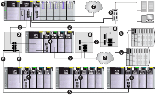
In this network example, the Ethernet backplane (1) includes a and a BMENOC0301/11 communications module. The PAC is connected to both the main ring (2) and a control network (9). The BMENOC0301/11 is connected to a distributed device cloud (7):
1
main rack (including a PAC and a BMENOC0301/11 module)
2
main RIO ring
3
DRS connected to the RIO main ring and RIO sub-ring
4
Ethernet RIO drops (which include a BM•CRA312•0 (e)X80 EIO adapter module)
5
RIO sub-ring
6
DRSs configured for copper-to-fiber and fiber-to-copper transition connect a DIO cloud (7) and a DIO sub-ring (8) to the main RIO ring)
7
DIO cloud
8
DIO sub-ring
9
control network (connected to the PAC in the local rack)
NOTE:
A BMENOC0301/11 module can support distributed equipment via its Ethernet backplane connection to the CPU and via its device network port(s) on the front panel, respecting the limitation of 128 devices scanned per BMENOC0301/11 module. Of these 128 devices:
When you use a BMENOC0301/11 Ethernet communications module on the Modicon M580 rack, observe these limits:
-
You can install a maximum of four communication modules (including, but not limited to, Ethernet communication modules) on the local rack (depending on the selected CPU). Only three can be BMENOC0301/11 modules.
-
Each BMENOC0301/11 module can manage a maximum of 112 distributed devices and 16 local slaves.
-
Because each BMENOC0301/11 on the Ethernet bus communicates with the CPU and every other BMENOC0301/11 on the rack, they are in the same network and thus transparency is provided.
NOTE: For some M580 Hot Standby systems that include RIO and DIO rings, disconnect the backplane port of the BMENOC0301/11 module. Refer to the Modicon M580 Hot Standby System Planning Guide for Frequently Used Architectures.
By default, Ethernet backplanes are disabled in both M580 standalone and Hot Standby systems. Therefore, a BMENOC03•1 module installed on the backplane in an M580 network, without enabling the Ethernet backplane port, is isolated from the network.
An isolated DIO network is not part of the RIO network. It is an Ethernet-based network containing distributed equipment on a copper wire running from a single port connection. If you use dual-port distributed equipment that support , you can connect the equipment in a daisy-chain loop to the two device network ports on a BMENOC0301/11 module. In M580 Hot Standby systems, isolate a DIO network by using a DIO ring.
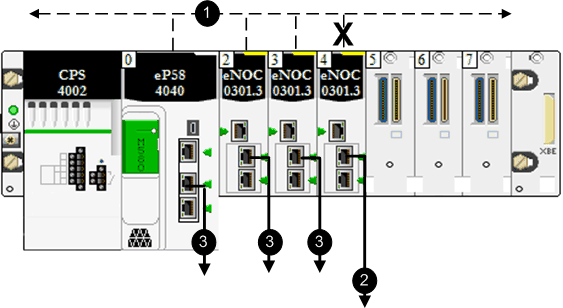
Use the Control Expert DTM to configure the BMENOC0301/11 module to manage an isolated DIO network. The X in this figure indicates that the connection between the Ethernet port on the last BMENOC0301/11 in the rack and the Ethernet bus is disabled to manage an isolated DIO network:
1
Ethernet communication on the backplane
2
connection to an isolated network
3
connection to a device network
To plan an isolated DIO network, connect the device network port (ETH 2, ETH 3) of the BMENOC0301/11 module to the DIO network.
NOTE: If you use dual-port equipment that support RSTP, you can connect the equipment in an isolated daisy chain loop to ports ETH 2 and ETH 3 on the BMENOC0301/11 modules.
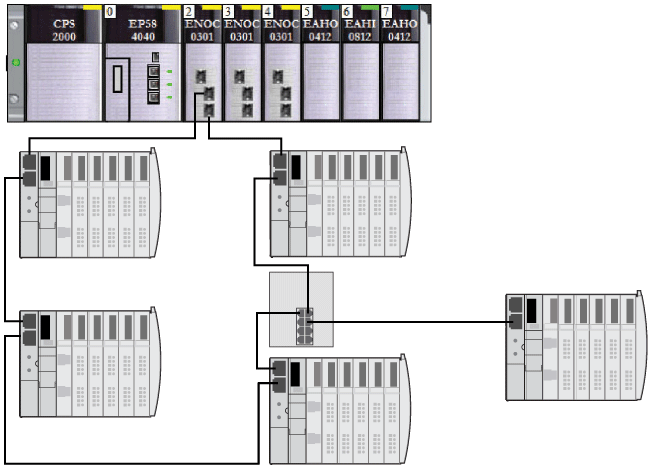
The BMENOC0301/11 can be connected as a dual attachment to a distributed network with daisy-chain loop topology that supports for cable redundancy:
Connect daisy chain loops to ports ETH 2 and ETH 3:
The Ethernet ports on the BMENOC0301/11 module function as both an Ethernet switch and an interface to the module. Information flows through the device to the STB islands in the loop.
Hot Standby Considerations
The Device DDT variables for EtherNet/IP and Modbus devices that contain freshness and input and output data are transferred from the primary CPU to the standby CPU. Thus, they are used to diagnose the health of the device and the associated data. DIO_HEALTH in the Device DDT for the BMENOC0301/11 can be used to diagnose connection health.
These actions occur during the switchover:
-
The connections to distributed devices close.
-
The BMENOC0301/11 modules swap their IP addresses. (The BMENOC0301/11 module on the new primary rack takes the configured IP address; the BMENOC0301/11 module on the new standby rack takes the configured IP address +1.)
-
The connections to distributed devices are re-established within these intervals:
This table shows the CPUs that are available for Modicon M580 Hot Standby systems. The table also shows the maximum number of all Ethernet communication modules, including BMENOC0301/11 modules, in the local rack with the different CPU references:
|
CPU
|
All Ethernet communication modules, including BMENOC0301/11 (on local rack)
|
|
BMEP582040, BMEH582040, BMEH58••••S
|
2
|
|
BMEP584040, BMEH584040, BMEH58••••S
|
3
|
|
BMEP586040, BMEH586040, BMEH58••••S
|
3
|
In an M580 Hot Standby system, the BMENOC0301/11 module uses the same IP+1 address as the BMENOC0321 control network module on the local rack. Confirm that you configure the IP address used in the BMENOC0301/11 module differently than the IP address of the BMENOC0321 module (for the control network and the fieldbus network when IP forwarding is enabled). Use an Ethernet network manager tool to verify the system is working.
NOTE: In an M580 Safety Hot Standby system or non-Safety system, follow these steps to upgrade the firmware in all communication modules configured on the local rack, including BMENO•03•• modules.
-
You can upgrade the firmware in all communication modules without stopping the process or application with these two steps:
-
First, connect UL to the communication module’s n + 1 address. Validate the connection to stop the standby CPU. Upgrade the communication module and run the CPU with UL
-
Second, swap your process and repeat the previous step.
-
When the CPU is in WAIT state, the communication module uses the
main IP address + 1. However, if both communication modules are in WAIT state, then one module uses the Main IP address while the other uses the main IP address + 1.
-
For detailed information about the configuration of M580 Hot Standby systems, refer to the Modicon M580 Hot Standby System Planning Guide for Frequently Used Architectures.
How to Help Avoid a Broadcast Storm
The following information
does not apply to BMENOC0301.4 (or later) modules; however, the content
does apply to earlier versions of BMENOC0301 modules and all versions of BMENOC0311 modules.
NOTE: In a Hot Standby system, you can install only one main ring, which connects to the CPUs’ Ethernet backplanes. If your system contains an RIO main ring or distributed equipment that is connected in a daisy chain loop to a non-isolated BMENOC0301/11 module on the local rack, verify that you isolate (disable the modules’ Ethernet backplane ports) other BMENOC0301/11 modules to which you connect a daisy chain loop of distributed equipment.
You can have multiple BMENOC0301/11 modules in a local rack, each with its backplane port enabled, provided the embedded switch ports (the service port and the two network ports) are not used.
 WARNING


 CAUTION