|
Installing a Module
|
|


|
Original instructions
|
|
Installing a Module
|
|
|
Original instructions
|
0BMX P34 2020 at rack position 0
1discrete I/O module at rack position 1
2counter module at rack position 2
3BMXNOR0200H module at rack position 3
4-7available rack positions
8extension module at rack position 8
 WARNING WARNING |
|
MODULE DESTRUCTION - LOSS OF APPLICATION
Disconnect all power to the rack before the installation of the BMXNOR0200H module.
Failure to follow these instructions can result in death, serious injury, or equipment damage.
|
|
Step
|
Action
|
Illustration
|
|---|---|---|
|
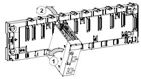
1
|
NOTE: Before installing a module, take off the protective cover from the module connector located on the rack. Position the two pins on the reverse side of the module (at the bottom) in the corresponding slots on the rack.
|
 |
|
2
|
Incline the module towards the top of the rack so that the module sits flush with the back of the rack. It is now set in position.
|
|
|
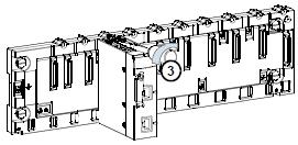
3
|
Tighten the mounting screw so that the module is held in place on the rack.
Tightening torque: 0.4...1.5 N•m (0.30...1.10 lbf-ft).
|
 |
|
WARNING |
|
UNINTENDED EQUIPMENT OPERATION
Check that the mounting screw is securely tightened to ensure the module is firmly attached to the rack.
Failure to follow these instructions can result in death, serious injury, or equipment damage.
|
