Introduction
The 171 CBU 78090, 171 CBU 98091 and 171 CBU 98091 processors support an I/O-Bus containing up to 32 Momentum devices. The I/O-Bus supports up to 256 input words, and 256 output words.
Monitoring I/O-Bus Health
The processor monitors the health of each module on the I/O-Bus, and stores health data in 2 system registers: %SW128 and %SW129. Each bit represents the health of a module on the I/O-Bus, as follows:
%SW128.0 stores the health of the module at address 1
%SW129.15 stores the health of the module at address 32
A bit value of 1 indicates a module is healthy.
I/O-Bus Branching
The processors support the use of 170 BNO 671 00 branch interface modules to create a single level of branches on the I/O-Bus.
Creating the I/O-Bus
To create an I/O-Bus, follow these steps:
Step |
Action |
|---|---|
1 |
In the , navigate to and double-click the node: 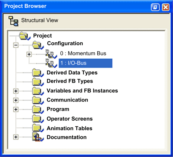 The window opens. |
2 |
In the window, right-click an empty connection point to display the context menu: 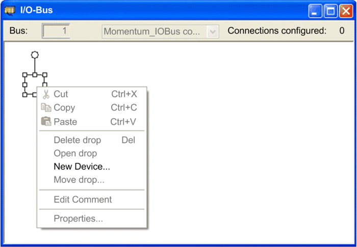 |
3 |
Select to open the window. 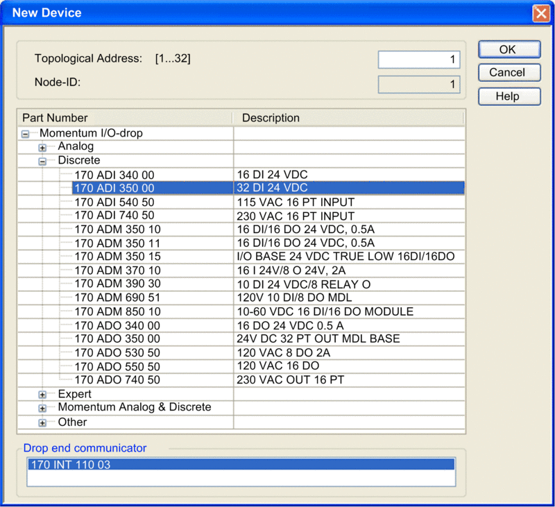 |
4 |
In the window, do the following:
NOTE:
|
NOTE: In place of steps
3 and 4, above, you can instead select a device in the and drop it
onto an empty connection point. The following version of the window opens:
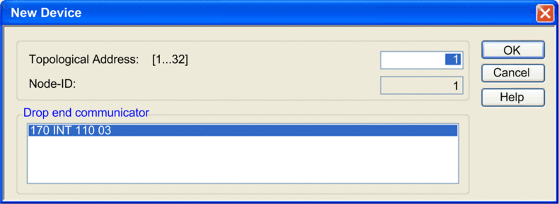 In this window, enter a and then click . |
|
5 |
In the window, the selected device–in this example the 170 ADI 350 00 module–is added: 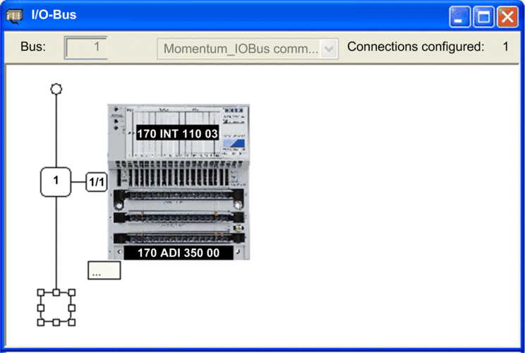 In the , the new I/O base, and communication module appear as a node on the I/O-Bus: 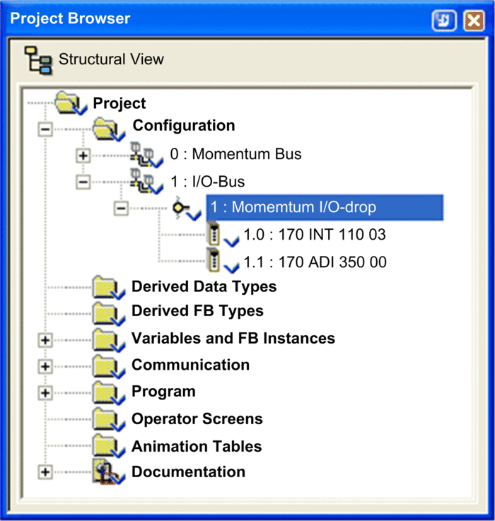 Click to retain your edits. |


