Configuring Modbus Slave Settings
Use Control Expert to configure serial ports on the 171 CBU 78090, 171 CBU 98090 and 171 CBU 98091 processors as Modbus slaves. The range of available settings depend on the port you are configuring:
the configurable RS232/RS485 serial port on the 171 CBU 78090, 171 CBU 98090 and 171 CBU 98091 processors, which operates at channel 0
the fixed RS485 serial port on the 171 CBU 78090 processor, which operates at channel 1
Serial Link Parameters
The following parameters can be configured in Control Expert for operation of the serial link in Modbus slave mode:
Parameter |
Fixed RS232 Port 171 CBU 78090 |
Configurable RS232/RS485 Port 171 CBU 98090 & 171 CBU 98091 |
|---|---|---|
Operation Mode |
Modbus (fixed) |
Modbus (fixed) |
Modbus type |
Slave (fixed) |
Slave (fixed) |
1...247, 248; default = 1 |
1...247, 248; default = 1 |
|
RS485 (fixed) |
|
|
RX/TX (fixed) |
|
|
– |
If RS232 and RX/TX + RTS/CTS DCE mode are selected:
default = 0 |
|
|
|
|
2...10,000 ms in 1 ms increments; default = 2 ms |
2...10,000 ms in 1 ms increments; default = 2 ms |
|
|
|
|
|
|
|
|
|
Slave Number
Use this parameter to input the processor slave number (or address):

Values include physical addresses 1 to 247, and 248 indicating Modbus slave point-to-point serial communication. Default = 1.
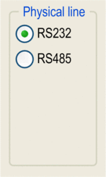
Physical Line
Use this parameter to select the physical line:

You can choose between 2 types of physical lines for the configurable serial port at port 2 on the processor:
RS232
RS485
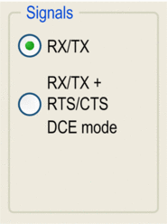
Signals
Use this parameter to select the signal used by the physical line:

For RS232 communication, selections include:
RX/TX (default)
RX/TX + RTS/CTS DCE mode (typically selected when the processor is connected to a modem or bridge)
If the RS485 is configured, the entire zone will be grayed out and the default value is RX/TX.
RTS/CTS Delay
This configuration parameter provides for a delay after a clear to send (CTS) frame has been received in response to a prior request to send (RTS) frame.
Configure this parameter by inputting a value into the screen element, below:

RTS/CTS delay zone is enabled only when both RS232 and RX/TX+RTS/CTS DCE mode are selected. An RTS/CTS flow control algorithm is selected if the default value is 0 ms. A value different from 0 enables an RTS/CTS modem control algorithm.
The RTS/CTS flow control algorithm (DTE <-> DTE) is different from the RTS/CTS modem control algorithm (DTE <-> DCE) as follows:
The RTS/CTS flow control algorithm is related to the overflow reception buffer (full-duplex).
The RTS/CTS modem control algorithm deals with the shared transmission process, for example, a radio modem.
These algorithms are used for the following purposes:
Algorithm |
Description |
|---|---|
RTS/CTS Flow Control |
The purpose of this algorithm is to help avoid a reception buffer overflow. The RTS output signal of each device is connected to CTS input signal of other device. The transmitter is authorized to transmit data when receiving the RTS input signal on its CTS input. This algorithm is symmetric and allows full-duplex asynchronous communication. |
RTS/CTS Modem Control |
Before a request is transmitted, the sender activates the RTS signal and waits for the CTS signal to be triggered by the modem. If the CTS is not activated after the RTS/CTS delay, the request is discarded. |
Transmission Speed
Use this parameter to select the transmission speed of the Modbus serial link:

Select a speed that is consistent with the other devices on the bus. The configurable values include 300, 600, 1200, 2400, 4800, 9600 (default), and 19200 bits per second.
Delay Between Frames
Use this parameter to set the minimum time separating two frames on reception:

The specified delay is added when the PLC is receiving messages. This is mainly used in RTU mode to extend the end of message frame timeout when using unbuffered modems or other devices that may add delays to the data transmission. Select to apply the default value.
Data
Use this parameter to enter the type of coding used to communicate over the Modbus serial link:

Set this field so that it is the same as the other devices connected on the bus. There are two settings:
RTU mode (default):
The characters are coded over 8 bits.
The end of the frame is detected when there is a silence of at least 3.5 characters.
The integrity of the frame is checked using a word known as the CRC checksum, which is contained within the frame.
ASCII mode:
The characters are coded over 7 bits.
The beginning of the frame is detected when the ":" character is received.
The end of the frame is detected by a carriage return and a line feed.
The integrity of the frame is checked using a byte called the LRC checksum, which is contained within the frame.
Stop
Use this parameter to enter the number of stop bits used for communication:

Set this field so that it is the same as the other devices on the bus. The configurable values include:
1 bit (default)
2 bits
Parity
Use this parameter to determine whether a parity bit is added or not, as well as its type:

Set this field so that it is the same as the other devices on the bus. The configurable values are:
Even (default)
Odd
None


