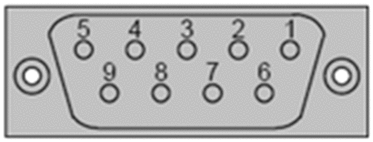
Pin Assignment
The I/O-Bus port uses a DB9 female connector.

The I/O-Bus signals assigned to each pin include:
I/O-Bus Pin Number |
Wire Color |
Signal |
|---|---|---|
1 |
Yellow |
DO (Data out) |
2 |
Gray |
DI (Data in) |
3 |
Brown |
Common |
4 |
– |
Not connected |
5 |
– |
Not connected |
6 |
Green |
DO_N (Data out negated) |
7 |
Pink |
DI_N (Data in negated) |
8 |
– |
Not connected |
9 |
– |
Not connected |
Low Profile Cables
For side-by-side mounting of the processor with I/O modules on a DIN rail or wall, Modicon provides two specially molded low profile cables.
Part Number |
Length |
|---|---|
170 MCI 007 00 |
11.4 cm (4.5 in) |
170 MCI 100 01 |
100 cm (39 in) |
These cables have a male 9-in D-shell connector on one end and a female 9-pin D-shell on the other. The male connector plugs into the female I/O-Bus port on the processor, and the female connector plugs into the male connector on the left side of a 170 INT 110 00 Interbus communications adapter on an I/O base. Additional cables can then be used to connect a series of I/O modules via their I/O-Bus communication ports.

I/O-Bus Cable Connector Kit
I/O-Bus communicates over full duplex cable. For custom cable lengths, Schneider Electric offers a cable connector kit (part number 170 XTS 009 00). The kit includes two connectors, one male and one female, that can be soldered to a full duplex cable of the appropriate length.
The recommended cable is Belden 8103 or equivalent.


