|
28-Pin Terminal Block Modules
|
|
|
|

|
Spring terminal blocks
|
Caged terminal blocks
|
||
|---|---|---|---|
|
Illustration
|
 |
 |
|
|
Number of wires accommodated
|
1
|
1
|
|
|
Number of wire gauges accommodated
|
minimum
|
0.25 mm2 (AWG 24)
|
|
|
maximum
|
1.5 mm2 (AWG 16)
|
||
|
Wiring constraints
|
The wires are connected by pressing on the button located next to each pin. To press on the button, you have to use a flat-tipped screwdriver with a maximum diameter of 3 mm.
|
Caged terminal blocks have slots that accept:
Caged terminal blocks have captive screws. On the supplied blocks, these screws are not tightened.
|
|
|
Maximum screw tightening torque
|
-
|
0.5 N•m (0.37 lb-ft).
|
|
|
Temperature range of wire
|
Minimum 105 °C
|
||
 DANGER DANGER |
|
ELECTRICAL SHOCK
The terminal block must be connected or disconnected with sensor and pre-actuator voltage switched off.
Failure to follow these instructions will result in death or serious injury.
|

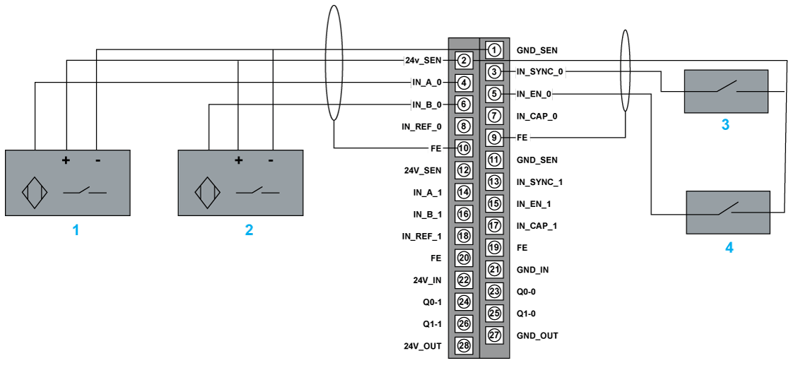
1IN_A input
2IN_B input
3IN_SYNC input (synchronization input)
4IN_EN input (enable input)

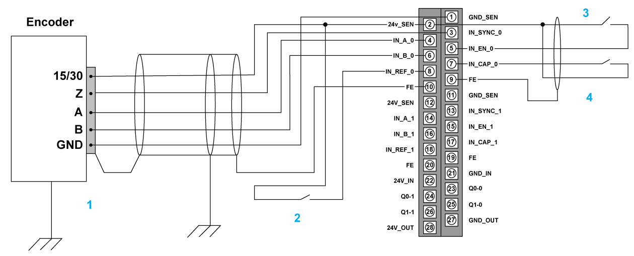
1Encoder (inputs A, B and Z)
2IN_REF input (homing input)
3IN_EN input (enable input)
4IN_CAP input (capture input)

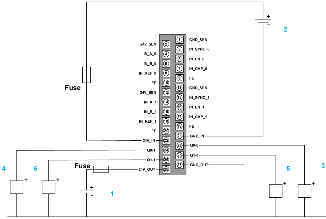
124 V supply for actuators
224 V supply for sensors
3Actuator for the Q0 output of counting channel 0
4Actuator for the Q1 output of counting channel 0
5Actuator for the Q0 output of counting channel 1
6Actuator for the Q1 output of counting channel 1