|
Ethernet Link
|
|
|
|
|
Characteristic
|
Description
|
Value
|
|---|---|---|
|
Di-electric strength
|
Ethernet
|
1,500 Vdc between logic common and twisted pair (@0…2,000 m altitude).
|
|
Ethernet port physical spec.
|
Connector Type
|
Dual shield RJ45 connectors
|
|
Speed
|
10Base-T, 100Base-TX
|
|
|
Auto Negotiation
|
Supported
|
|
|
Auto MDI/MDI-X
|
Supported
|
|
|
Addressing
|
Unique IEEE Global (MAC) Address. User assigned IP Address
|
|
|
Mode of Operation
|
Master/Slave, Half/Full duplex
|
|
|
Topology
|
Star, Daisy chain
|
|
|
Media
|
Copper (Twisted pair)
|
|
|
Isolation support
|
Yes
|

|
Label
|
Color
|
Description
|
|---|---|---|
|
ETH STS
|
Green
|
Indicates the Ethernet port operation states
|
|
LED
|
Pattern
|
Indication
|
|---|---|---|
|
ETH LNK/ACT (green)
|
on
|
Ethernet link is detected and there is no communication activity
|
|
off
|
No Ethernet link is detected
|
|
|
Flashing
|
Data exchange on the Ethernet link is in progress
|
|
|
ETH 100
|
green
|
Ethernet transmission is at 100 Mbits/s (Fast Ethernet)
|
|
yellow
|
Ethernet transmission is at 10 Mbits/s
|
|
|
off
|
No link is detected
|
|
|
ETH STS (green): Ethernet communication status
|
off
|
No communication activity
|
|
on
|
Communication is OK
|
|
|
2 flashes
|
Invalid MAC address
|
|
|
3 flashes
|
Ethernet link is not connected
|
|
|
4 flashes
|
Duplicate IP Address
|
|
|
5 flashes
|
Waiting for server IP address
|
|
|
6 flashes
|
Safe Mode - At default IP address
|
|
|
7 flashes
|
Configuration conflict between rotary switches and internal configuration
|
|
Label
|
Color
|
Description
|
|---|---|---|
|
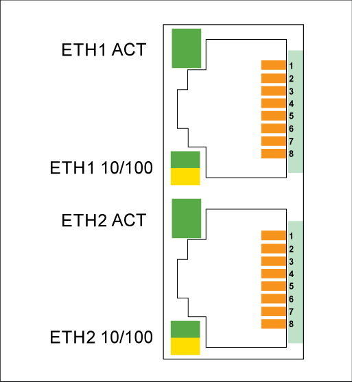
ETH1 ACT
|
Green
|
Indicates the activity of Ethernet port1
|
|
ETH1 10/100
|
Green
|
Indicates the speed of Ethernet port1 which is 100 Mbps
|
|
Yellow
|
Indicates the speed of Ethernet port1 which is 10 Mbps
|
|
|
ETH2 ACT
|
Green
|
Indicates the activity of Ethernet port2
|
|
ETH2 10/100
|
Green
|
Indicates the speed of Ethernet port2 which is 100 Mbps
|
|
Yellow
|
Indicates the speed of Ethernet port2 which is 10 Mbps
|
|
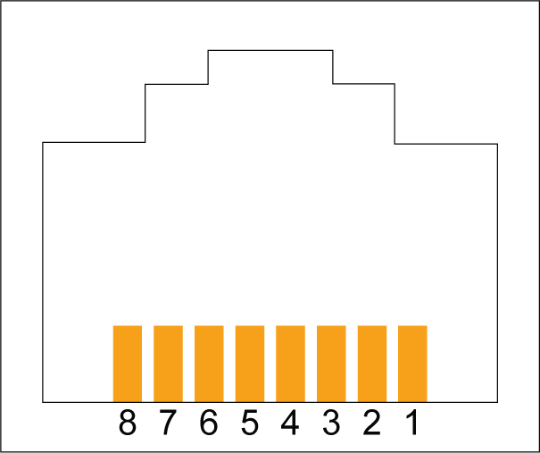
Pin No.
|
Signal Name
|
|---|---|
|
1
|
TD+
|
|
2
|
TD-
|
|
3
|
RD+
|
|
4
|
Not connected
|
|
5
|
Not connected
|
|
6
|
RD-
|
|
7
|
Not connected
|
|
8
|
Not connected
|
|
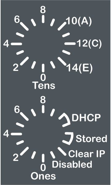
Rotary Switch
|
Numbers
|
Description
|
|---|---|---|
|
Upper switch
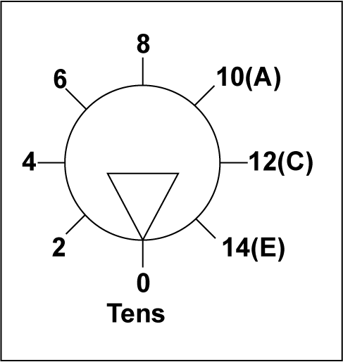 |
0…9
|
Tens value for the device name (0, 10, 20, …, 90)
|
|
10(A)…15(F)
|
Tens value for the device name (100, 110, 120, …, 150)
|
|
|
Lower switch
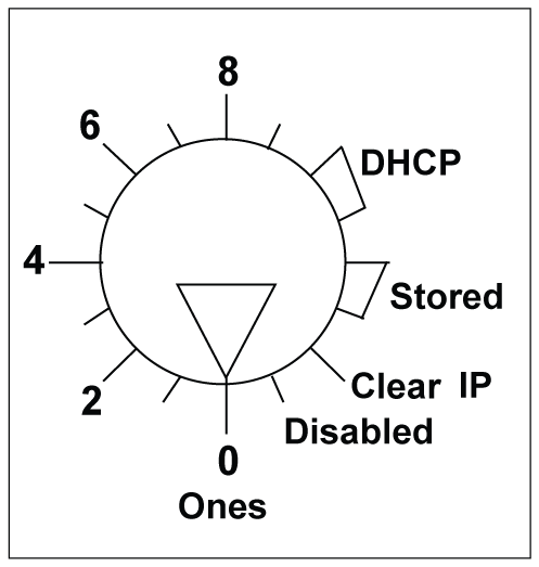 |
0…9
|
Ones value for the device name (0, 1, 2, …, 9)
|
|
DHCP
|
Set the lower rotary switch to one of its DHCP positions to perform a DHCP request that has a MAC address as Client Identify.
|
|
|
Stored
|
The lower rotary switch is set to STORED (default setting) to use the application’s configured parameters.
NOTE: When the Device Name is empty, MC80 will use MAC address to get IP address. |
|
|
Clear IP
|
The lower rotary switch is set to CLEAR IP to use the MAC-based default IP address.
The default IP address format is 10.10.x.x
|
|
|
Disabled
|
Set the switch to Disabled to disable communications.
|
|
|
Device Name Naming Rules
|
||
|
There are three components of the device name. The default device name of the module is:
BMK C80 20310 : BMK_20310_xxy
The numeric value between 00 and 159 is set on the rotary switches. (For the default device name, xx is the value of the upper rotary switch and y is the value of the lower rotary switch.)
For example: For a BMK C80 20310 module, values of 120 (12 x 10) and 6 (6 x 1) on the respective upper and lower rotary switches indicate a value of 126. The value is appended to the default device name (BMK_20310_xxy) to create the valid DHCP device name of BMK_20310_126.
|
||