|
General Characteristics of the Processor
|
|
|
|
|
BMK C80 20310
|
BMK C80 20301
|
BMK C80 30311
|
|
|---|---|---|---|
|
Number of Discrete Inputs
|
8 standard + 12 from HSC channels
|
8 standard
|
8 standard + 12 from HSC channels
|
|
Number of Discrete Outputs
|
8 standard + 4 from HSC channels
|
12 standard (2.0 A)
|
12 standard (2.0 A) + 4 from HSC channels
|
|
Number of Analog Inputs
|
-
|
4
|
4
|
|
Number of High Speed Counter
|
2 channels (6 DI and 2 DO per channel)
|
-
|
2 channels (6 DI and 2 DO per channel)
|
|
Modbus connection
|
X
|
X
|
X
|
|
Integrated CANopen master connection
|
X
|
X
|
X
|
|
Integrated Ethernet connection
|
X
|
X
|
X
|
|
X: Accessible function
-: Inaccessible function
|
|||
|
Processor
|
BMK C80 •••••
|
||
|---|---|---|---|
|
Description
|
RS232/RS485, USB, Serial port, Ethernet, CANopen
|
||
|
Retention memory capacity
|
128 kB
|
||
|
User application memory
|
3,584 kB
|
||
|
RTC
|
Accuracy
|
Powered
|
16 minutes per year @25 °C (without calibration)
|
|
Non-powered
|
12 seconds per 72 hours @25 °C (retention duration)
|
||
|
Retention time
|
72 hours
|
||
|
Battery
|
Without
|
||
|
USB physical spec.
|
Type
|
USB2.0 Device
|
|
|
Speed mode
|
Full speed mode (12 Mbps)
|
||
|
Serial port
|
RJ45, RS232/RS485.
300…19,200 bps
Modbus slave, Modbus master RTU/ASCII, Character mode.
|
||
|
Ethernet port
|
2
|
||
|
CANopen
|
Up to 16 devices
|
||
|
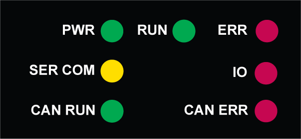
LED display
|
PWR (green)
RUN (green)
ERR (red)
SER COM (yellow)
IO (red)
CAN RUN (green)
CAN ERR (red)
ETH STS (green)
|
||
|
Real-time Clock
|
Date and time with 1 ms resolution (resolution is 1 sec when power is off).
|
||

|
Label
|
Color
|
Description
|
|---|---|---|
|
PWR
|
Green
|
Indicates the power supply status
|
|
RUN
|
Green
|
Indicates the module operation status
|
|
ERR
|
Red
|
Indicates the detected errors of the module
|
|
IO
|
Red
|
Indicates the detected error on IO ports
|
|
RUN
|
ERR
|
IO
|
CPU State
|
||
|---|---|---|---|---|---|
|
B
|
B
|
B
|
The CPU is booting or executing power on self tests or detects an invalid or missing OS.
|
||
|
0
|
B
|
0
|
The CPU is not configured
|
||
|
B
|
0/B
|
0/S
|
The CPU is in stop state.
|
||
|
ERR LED
|
blinking
|
if non fatal error is detected
|
|||
|
off
|
if the error is not detected.
|
||||
|
IO LED
|
solid
|
if there is an IO error.
|
|||
|
off
|
if there is no IO error.
|
||||
|
S
|
0/B
|
0/S
|
The CPU is in RUN mode.
|
||
|
0
|
S
|
S
|
The Fatal error is detected and the CPU has permanent reset, no communication is available.
|
||
|
B
|
S
|
0
|
Firmware download is in progress
|
||
|
A LED can have three states: solid, off, or blinking at 2 Hz (time on = time off = 250 ms). When the product is powered, there is at least one LED in Solid or Blinking state, irrespective of the CPU state.
|
|||||