Discrete I/O Function (8 Input 8 Output) and Channel Status Display
 
Description
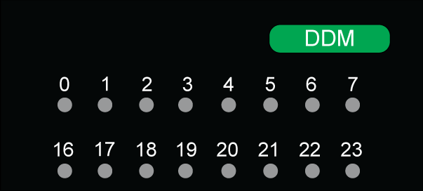
The Discrete I/O functions are equipped with a display block featuring LEDs that displays the functions channel status and the overall function status.
Representation
The below figure shows the LED indicator of the Discrete I/O function:
NOTE: The mixed input/output function has two groups of eight channels. The input group is represented by channels 0…7 and the output group is represented by channels 16…23.
The following table helps you to perform diagnostics of the discrete I/O function status according to the channel LEDs:
Status
Meaning
0...7
16...23
ON
-
Voltage is present on the input channel
-
ON
Voltage is present on the output channel
-
BLK
Actuator supply fails
-
FLK
Output channel is overload/short-circuit
Legends
-
Not applicable
ON
LED is steady on
BLK (Blinking)
The LED is turned on for 200 ms, then turned off for 200 ms
FLK (Flickering)
The LED is turned on for 50 ms, then turned off for 50 ms
NOTE:
  • Display of internal or external events is effective once the module is configured.
  • When an event is detected, the channel status is recorded until the cause of the event is cleared.
  • The output channel is closed by default.
WARNING
CHANNEL LED INFORMATION NOT MATCHING SENSORS VALUE
After a sensor power outage:
  • Do not take into account the input LEDs information (they show the last recorded value of the sensors, not their real value).
  • Check the real positions on the sensors.
Failure to follow these instructions can result in death, serious injury, or equipment damage.