|
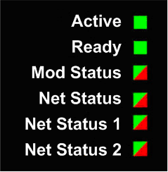
LED Indicators on the 140 NOP 850 00 Module
|
|
|
(Original Document)
|

|
Description
|
Active4
|
Ready
|
Mod Status
|
Net Status
|
Net Status 1
|
Net Status 2
|
|||||
|---|---|---|---|---|---|---|---|---|---|---|---|
|
Green
|
Green
|
Green
|
Red
|
Green
|
Red
|
Green
|
Red
|
Green
|
Red
|
||
|
General
|
Component not operating
|
—
|
Off
|
Off
|
On
|
—
|
—
|
—
|
—
|
—
|
—
|
|
Invalid configuration
|
—
|
Off
|
Off
|
Flash
|
—
|
—
|
—
|
—
|
—
|
—
|
|
|
Not configured
|
—
|
—
|
Flash
|
Off
|
—
|
—
|
—
|
—
|
—
|
—
|
|
|
Configured
|
—
|
Blink
|
On
|
Off
|
on/flash
|
Off
|
on/flash
|
Off
|
on/flash
|
Off
|
|
|
no/default module MAC
|
—
|
Blink 2
|
Off
|
Flash
|
Off
|
Off
|
Off
|
Off
|
Off
|
Off
|
|
|
no/default port MAC
|
—
|
Blink 2
|
Off
|
Flash
|
Off
|
Off
|
Off
|
Off
|
Off
|
Off
|
|
|
Power-up
|
Sequence
|
5
(On 0.25 sec. Off 0.25 sec)
|
6
(On 0.25 sec. Off 0.25 sec)
|
1
(Green on 0.25 sec. Green off. Red on 0.25 sec; Red off. Green on)
|
2
(Green on 0.25 sec. Green off. Red on 0.25 sec; Red off. Green on)
|
3
(Green on 0.25 sec. Green off. Red on 0.25 sec; Red off. Green on)
|
4
(Green on 0.25 sec. Green off. Red on 0.25 sec; Red off. Green on)
|
||||
|
61850 protocol
|
No connections or all connections closed
|
—
|
On
|
On
|
Off
|
Flash
|
Off
|
Flash
|
Off
|
Flash
|
Off
|
|
Connected
|
—
|
On
|
On
|
Off
|
On
|
Off
|
On
|
Off
|
On
|
Off
|
|
|
IP status
|
No Ethernet links
|
—
|
Blink 3
|
—
|
—
|
Off
|
On
|
Off
|
On
|
Off
|
On
|
|
Duplicate IP1
|
—
|
Blink 4
|
—
|
—
|
Off
|
On
|
Off
|
On
|
Off
|
On
|
|
|
Waiting for IP
|
—
|
Blink 5
|
On
|
Off
|
Off
|
Off
|
Off
|
Off
|
Off
|
Off
|
|
|
Default IP address2
|
—
|
Blink 6
|
On
|
Off
|
Off
|
Off
|
Off
|
Off
|
Off
|
Off
|
|
|
Configured IP address assigned
|
—
|
On
|
On
|
Off
|
Flash
|
Off
|
Flash
|
Off
|
Flash
|
Off
|
|
|
Invalid configuration
|
—
|
Blink 7
|
On
|
Off
|
Off
|
Off
|
Off
|
On
|
Off
|
Off
|
|
|
Routing Service
|
Duplicate IP1
|
—
|
Blink 4
|
On
|
Off
|
On
|
Off
|
Flash
|
Off
|
Off
|
On
|
|
Waiting for IP3
|
—
|
Blink 5
|
On
|
Off
|
Off
|
Off
|
On
|
Off
|
Off
|
Off
|
|
|
Default IP2
|
—
|
Blink 6
|
On
|
Off
|
Off
|
Off
|
Off
|
Off
|
Off
|
Off
|
|
|
Receive or assign IP
|
—
|
On
|
On
|
Off
|
Flash
|
Off
|
Flash
|
Off
|
Flash
|
Off
|
|
|
Invalid configuration
|
—
|
Blink 7
|
On
|
Off
|
Off
|
Off
|
Off
|
Off
|
Off
|
Off
|
|

|
Name
|
Color
|
Status
|
Description
|
|---|---|---|---|
|
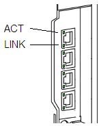
LINK (ETH 1 and ETH 2)
|
Green
|
On
|
100 Mbit/s link detected
|
|
Yellow
|
On
|
10 Mbit/s link detected
|
|
|
—
|
Off
|
No detected link
|
|
|
LINK (ETH 3 and ETH 4)
|
Green
|
On
|
1000 Mbit/s link detected
|
|
Yellow
|
On
|
10 Mbps or 100 Mbps link detected
|
|
|
—
|
Off
|
No detected link
|
|
|
ACT
|
Green
|
Blinking
|
Active Ethernet link (transmit or receive detected)
|
|
—
|
Off
|
Inactive Ethernet link
|