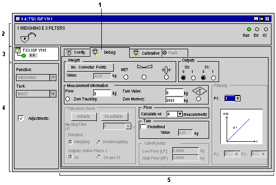
Description of the Weighing Application Function Debug Screen
(Original Document)
Introduction
The debug screen can be used to display weighing information and adjust certain parameters.
Illustration
This screen can be only accessed in online mode.
Description
The following table shows the various parts of the debug screen and their functions.
Address
Element
Function
1
Tab
The tab in the foreground indicates the current mode (Debug for this example). Each mode may be selected by the corresponding tab.
2
Module zone
Shows the abbreviated name of the module.
In online mode, this zone also contains the three LEDs Run, Err and IO.
3
Channel field
Is used:
  • By clicking on the reference number, to display the tabs:
    • Description, which gives the characteristics of the device.
    • I/O Objects, which is used to presymbolize the input/output objects.
    • Fault, which shows errors detected in the module (in online mode).
  • To select the channel,
  • To display the Symbol, name of the channel defined by the user (using the variable editor).
4
General parameters zone
Comprises:
  • the dropdown Function menu,
  • the dropdown Task menu defining the task (MAST or FAST) in which the implicit exchange objects of the channels will be exchanged.
  • the Adjustments check box: allows you to access the adjustment functions. When this box is ticked, an extra zone is added to the debug screen giving access to the parameters.
5
Display and adjustment zones
Display weighing information and adjust certain module parameters.