|
How to Modify the Threshold Check
|
|
|
(Original Document)
|
|
Designation
|
Description
|
|---|---|
|
Active
|
Discrete output management is operational if this box is checked.
It is not checked by default.
|
|
Direction
|
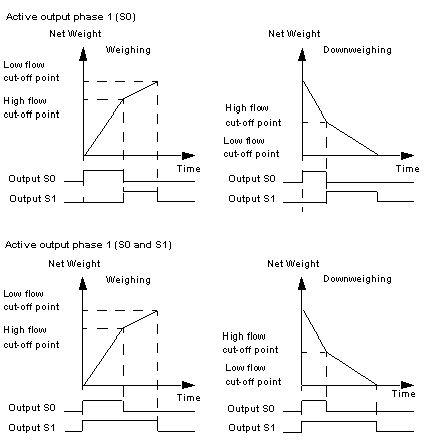
The detection direction corresponds to the direction in which the thresholds are recognized, i.e.:
This is the concept of exceeding by a greater value, in the case of weighing, or by a lower value, in the case of downweighing.
By default, Weighing is selected.
|
|
Phase 1 Active Outputs
|
The choice concerns the control of the S0 output on its own, or the S0 and S1 outputs at the same time.
See the explanation that follows.
By default, the module only activates S0 in the first phase.
|
|
Cut-off Points
|
The measurement can be associated with 2 thresholds for the following dosages: A High Flow cut-off point and a Low Flow cut-off point.
Depending on the logic defined, the S0 and S1 outputs go to zero when these thresholds are met.
The threshold values allowed lie between 0 and the maximum range. They are expressed in high resolution (one hundredth of a physical unit with fixed decimal point).
|
|
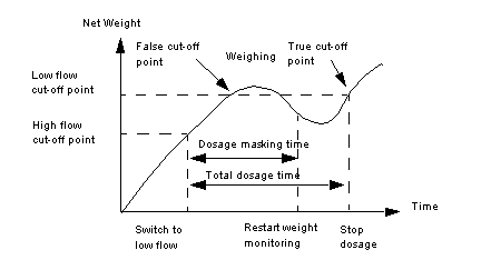
LF (Low Flow) Mask Time
|
It defines the time after the high flow cut-off, during which the module no longer checks the Weight/Threshold;
This is to mask the overshoot caused when the product has a drop in voltage. The values allowed lie between 0 and 1.5 seconds per 1/10th second step.
See the explanation that follows.
By default, this time is zero.
|


|
Step
|
Action
|
|---|---|
|
1
|
Access the weighing module configuration screen.
|
|
2
|
If necessary check the Active box in the Threshold check field to activate this function.
|
|
3
|
Check the selection boxes corresponding to the detection direction (Weighing or Downweighing) and to the phase 1 active outputs (S0 or S0 and S1).
|
|
4
|
Enter the Low flow and High flow in the Breaking points field.
|
|
5
|
Using the drop-down menu in the Threshold check field, select the PD masking time.
|
|
6
|
Confirm the modification with the command Edit → Validate.
|