|
|
(Original Document)
|
|
Name in LL984 Editor
|
Function Block Name
|
|---|---|
|
name of legacy 984 instruction
|
name in other tools and editors like:
|
 |
 |
 WARNING WARNING |
|
UNINTENDED EQUIPMENT OPERATION
Use only State RAM addressing (instead of topological addressing), if you want to detect forced bits by using L9_DISA.
L9_DISA does not detect forced coils and inputs (%Ix, %Qx), if forcing has been done by using topological addressing (e.g. %I0.4.1).
Failure to follow these instructions can result in death, serious injury, or equipment damage.
|

|
Input Pin
|
Name
|
Data Type
|
Address Range
|
Meaning
|
|---|---|---|---|---|
|
Top
|
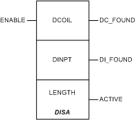
ENABLE
|
–
|
ON = enables operation
|
|
Node
|
Node Type
|
Name
|
Data Type
|
Address Range
|
Meaning
|
|---|---|---|---|---|---|
|
Top
|
IN/OUT
|
DCOIL
|
ANY_ARRAY_UINT
|
%MW
|
table with the number and addresses of disabled coils found
|
|
Middle
|
IN/OUT
|
DINPT
|
ANY_ARRAY_UINT
|
%MW
|
table with the number and addresses of disabled inputs found
|
|
Bottom
|
IN
|
LENGTH
|
UINT
|
1...100
|
table length (number of words used for the table)
valid range: 1 to 100
NOTE: If LENGTH=1 only the number of disabled inputs is displayed. |
|
Output Pin
|
Name
|
Data Type
|
Address Range
|
Meaning
|
|---|---|---|---|---|
|
Top
|
DC_FOUND
|
BOOL
|
–
|
ON = disabled coils are found
|
|
Middle
|
DI_FOUND
|
BOOL
|
–
|
ON = disabled inputs are found
|
|
Bottom
|
ACTIVE
|
BOOL
|
–
|
Echoes state of the top input (ENABLE).
|

|
Address
|
Value
|
Meaning
|
|---|---|---|
|
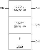
%MW100
|
3
|
indicates 3 disabled coils
|
|
%MW101
|
7
|
coil %M7 is disabled
|
|
%MW102
|
11
|
coil %M11 is disabled
|
|
%MW103
|
1247
|
coil %M1247 is disabled
|
|
%MW110
|
12
|
indicates 12 disabled inputs
|
|
%MW111
|
1
|
input %I1 is disabled
|
|
%MW112
|
9
|
input %I9 is disabled
|
|
%MW113
|
15
|
input %I15 is disabled
|
|
%MW114
|
18
|
input %I18 is disabled
|
|
%MW115
|
25
|
input %I25 is disabled
|
|
%MW116
|
293
|
input %I293 is disabled
|
|
%MW117
|
768
|
input %I768 is disabled
|
|
%MW118
|
901
|
input %I901 is disabled
|