Example (L9_MRTM)
(Original Document)
Introduction
The following section provides a detailed explanation of the L9_MRTM function block.
The program listed below loads words 00 through 14 of the ASCII basic module, using the L9_MRTM function block.
Hardware
Hardware required for this example (LL984 and associated equipment):
Memory Traffic Copped
Equipment
Memory
B885-001
%IW1 through %IW6
%MW1 through %MW6
B805-016
%I1 through %I16
Control Table
The following is the control table for this example:
Address
Value
Description
%MW50
0000
reserved for future use
%MW51
0001
first %MW word traffic copped from LL984 to ASCII basic module
%MW52
0001
%IW word where echo occurs
%MW53
-
L9_MRTM-controlled word for program table pointer
%MW54
-
L9_MRTM-controlled error codes
Program Table
The following is the program table for this example:
Address
Value
Description
%MW100
0103
%MW103 = start of instruction blocks
%MW101
0120
%MW120 = end of program table
%MW102
-
reserved
%MW103
2500
instruction block #1
Command: Load words 00 through 04 into ASCII basic module
%MW104
0001
%MW105
0002
%MW106
0003
%MW107
0004
%MW108
0005
%MW109
2505
instruction block #2
Command: Load words 05 through 09 into ASCII basic module
%MW110
0006
%MW111
0007
%MW112
0008
%MW113
0009
%MW114
0010
%MW115
2510
instruction block #3
Command: Load words 10 through 14 into ASCII basic module
%MW116
0011
%MW117
0012
%MW118
0013
%MW119
0014
%MW120
0015
Function Block Operation
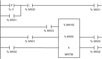
Referring to the network in graphic below, when contact %I1 is toggled on, coil %M501 is energized and the coil is maintained through the parallel rung consisting of contact %M501.
This applies power to the TRANSFER input of the function block, through contact %M501, causing the L9_MRTM to step through a cycle.
The content of block #1 is moved to words %MW1 through %MW6.
This action causes the COMPLETE output to raise for 1 scan and energize coil %M500.
Energizing coil %M500 causes the first rung to open, de-energizing coil %M501.
The lowering of contact %M501 removes the power to the TRANSFER input of the function block, thus disabling the function block.
The pointer value is incremented by 6 and is stored in the fourth word of the control table (%MW53).
NOTE: On initial start-up, power must be applied to the RESET input.
As a result of the data transfer, the %MW1 through %MW6 words are output to the B885-001 ASCII basic module.
The B885-001 module evaluates the data and sends back an echo of the command and data words to words %IW1 through %IW6.
The second time that contact %I1 is toggled on, coil %M501 is energized again and the coil is maintained through the parallel rung.
Power is re-applied to the TRANSFER input and the L9_MRTM tests word %IW1 to be equal with word %MW1.
If words %IW1 and %MW1 are not equal, contact %M501 remains latched and the L9_MRTM will continue to test the words each scan.
Block #2 will not be transferred until the 2 words are equal.
If the words are equal the L9_MRTM transfers the contents of block #2 to words %MW1 through %MW6.
This causes the COMPLETE output to raise and energize coil %M500, causing coil %M501 to de-energize. The pointer value is incremented by 6 and is stored in the fourth word of the control table (%MW53).
As a result of the second transfer, the %MW1 through %MW6 words are output to the B885-001 ASCII basic module. The module evaluates the data and sends back an echo of the command and data words.
To complete the transfer, contact %I1 is toggled on, coil %M501 is energized again.
The TRANSFER input is enabled and the L9_MRTM tests word %IW1 to be equal with word %MW1.
When the transfer is permitted, the L9_MRTM transfers the contents of block #3 to words %MW1 through %MW6.
The COMPLETE output is raised and energizes coil %M500, causing coil %M501 to de-energize.
The pointer value is incremented to the end of the table plus 1, which causes the END output to raise and energize coil %M502.
Contact %M502 applies power to the RESET input of the function block, resetting the L9_MRTM.