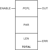
|
|
(Original Document)
|
|
Name in LL984 Editor
|
Function Block Name
|
|---|---|
|
name of legacy 984 instruction
|
name in other tools and editors like:
|
 |
 |

|
Input Pin
|
Name
|
Data Type
|
Address Range
|
Meaning
|
|---|---|---|---|---|
|
Top
|
ENABLE
|
–
|
ON = enables process control function
|
|
Node
|
Node Type
|
Name
|
Data Type
|
Address Range
|
Meaning
|
|---|---|---|---|---|---|
|
Middle
|
IN/OUT
|
PAR
|
ARRAY[1...28] OF UINT
|
%MW
|
see Parameter PAR below
|
|
Bottom
|
IN
|
LEN
|
UINT
|
28
|
length of parameter block (can not be changed)
|
|
Output Pin
|
Name
|
Data Type
|
Address Range
|
Meaning
|
|---|---|---|---|---|
|
Top
|
OUT
|
BOOL
|
–
|
ON = operation successful
|
|
Bottom
|
ERR
|
BOOL
|
–
|
ON = operation not successful
|
|
Word
|
Content
|
Format
|
|---|---|---|
|
1, 2
|
live input
|
REAL (Floating Point)
|
|
3
|
output status
|
UINT
|
|
4
|
input status
|
UINT
|
|
5
|
time word
|
UINT
|
|
6
|
reserved
|
UINT
|
|
7, 8
|
time (in ms) since last solve
|
DINT
|
|
9, 10
|
solution interval (in ms)
|
DINT
|
|
11, 12
|
last input, X_1
|
REAL (Floating Point)
|
|
13, 14
|
reset value
|
REAL (Floating Point)
|
|
15, 16
|
set point, target
|
REAL (Floating Point)
|
|
17, 18
|
set point, trickle flow
|
REAL (Floating Point)
|
|
19, 20
|
% of full flow for trickle flow set point
|
REAL (Floating Point)
|
|
21, 22
|
full flow
|
REAL (Floating Point)
|
|
23, 24
|
remaining amount to SP
|
REAL (Floating Point)
|
|
25, 26
|
resulting sum
|
REAL (Floating Point)
|
|
27, 28
|
output for final control element
|
REAL (Floating Point)
|
|
Control Expert-IEC bits
|
Function
|
|---|---|
|
0...7
|
standard output bits (flags)
|
|
8
|
1 = parameter(s) out of range
|
|
9
|
1 = overshoot past set point
more than 5% of (target set point - trickle flow set point
|
|
10
|
1 = totalizer running
|
|
11
|
1 = operation done
|
|
12...13
|
0 0 = OFF
0 1 = trickle flow
1 0 = full flow
|
|
14...15
|
not used
|
|
Control Expert-IEC bits
|
Function
|
|---|---|
|
0...7
|
not used
|
|
8
|
1 = use auxiliary trickle flow set point
|
|
9
|
1 = deviation set point
0 = absolute set point
|
|
10
|
1 = halt integration
|
|
11
|
1 = reset sum
|
|
12...15
|
standard input bits (flags)
|