|
Description
|
|
|
(Original Document)
|
|
Name in LL984 Editor
|
Function Block Name
|
|---|---|
|
name of legacy 984 instruction
|
name in other tools and editors like:
|
 |
 |

|
Variable
|
Meaning
|
|---|---|
|
YP
|
P component (only if PAR.fsIn.7 = 1)
|
|
YI
|
I component (only if PAR.fsIn.6 = 1)
|
|
YD
|
D component (only if PAR.fsIn.5 = 1)
|

|
Input Pin
|
Name
|
Data Type
|
Address Range
|
Meaning
|
|---|---|---|---|---|
|
Top
|
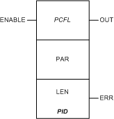
ENABLE
|
–
|
ON = enables process control function
|
|
Node
|
Node Type
|
Name
|
Data Type
|
Address Range
|
Meaning
|
|---|---|---|---|---|---|
|
Middle
|
IN/OUT
|
PAR
|
ARRAY[1...44] OF UINT
|
%MW
|
see Parameter PAR below
|
|
Bottom
|
IN
|
LEN
|
UINT
|
44
|
length of parameter block (can not be changed)
|
|
Output Pin
|
Name
|
Data Type
|
Address Range
|
Meaning
|
|---|---|---|---|---|
|
Top
|
OUT
|
BOOL
|
–
|
ON = operation successful
|
|
Bottom
|
ERR
|
BOOL
|
–
|
ON = operation not successful
|
|
-
|
Word
|
Content
|
Format
|
|---|---|---|---|
|
General Parameters
|
1, 2
|
live input, x
|
REAL (Floating Point)
|
|
3
|
output status, high and low limits exceeded
output status
|
WORD
|
|
|
4
|
output status, detected error in derivative time, negative integral time, or high/low limit settings
|
WORD
|
|
|
5
|
reserved
|
WORD
|
|
|
6
|
input status (standard input bits, manual, halt, reverse, direct)
input status
|
WORD
|
|
|
Input parameters
|
7, 8
|
set point, SP
|
REAL (Floating Point)
|
|
9, 10
|
manual output
|
REAL (Floating Point)
|
|
|
11, 12
|
summing junction, bias
|
REAL (Floating Point)
|
|
|
Outputs
|
13, 14
|
calculated control difference (calculated error value), XD
|
REAL (Floating Point)
|
|
15
|
previous operating mode (not used)
|
UINT
|
|
|
16, 17
|
elapsed time delta T (in ms) since last solve
|
UDINT
|
|
|
18, 19
|
previous system deviation, XD_1
|
REAL (Floating Point)
|
|
|
20, 21
|
previous input, X_1
|
REAL (Floating Point)
|
|
|
22, 23
|
integral part of output YI
|
REAL (Floating Point)
|
|
|
24, 25
|
differential part of output YD
|
REAL (Floating Point)
|
|
|
26, 27
|
proportional part of output YP
|
REAL (Floating Point)
|
|
|
28
|
previous operating status (not used)
|
UINT
|
|
|
Timing Information
|
29, 30
|
10 ms clock at time n
|
UDINT
|
|
31, 32
|
solution interval (in ms) (not used)
|
UDINT
|
|
|
Input parameters
|
33, 34
|
proportional gain, KP
|
REAL (Floating Point)
|
|
35, 36
|
reset time, TI (in sec)
|
REAL (Floating Point)
|
|
|
37, 38
|
derivative action time, TD (in sec)
|
REAL (Floating Point)
|
|
|
39, 40
|
high limit on output Y
|
REAL (Floating Point)
|
|
|
41, 42
|
low limit on output Y
|
REAL (Floating Point)
|
|
|
Output
|
43, 44
|
manipulated output variable, Y
|
REAL (Floating Point)
|
|
Control Expert-IEC bits
|
Function
|
|---|---|
|
0...7
|
standard output bits (flags)
|
|
8...12
|
for internal use
|
|
13
|
1 = high limit exceeded
|
|
14
|
1 = low limit exceeded
|
|
15
|
error detected
|
|
Control Expert-IEC bits
|
Function
|
|||||
|---|---|---|---|---|---|---|
|
5...15
|
not used
|
|||||
|
0...4
|
detected error conditions
|
|||||
|
Bit 4
|
Bit 3
|
Bit 2
|
Bit 1
|
Bit 0
|
Condition
|
|
|
1
|
0
|
1
|
1
|
1
|
negative derivative time constant
|
|
|
1
|
0
|
1
|
1
|
0
|
negative integral time constant
|
|
|
1
|
0
|
1
|
0
|
1
|
high/low limit error detected (low > high)
|
|
|
1
|
0
|
1
|
0
|
0
|
KP is negative
|
|
|
Control Expert-IEC bits
|
Function
|
|---|---|
|
0
|
1 = reverse action for loop output
0 = direct action for loop output
|
|
1...3
|
not used
|
|
4
|
1 = solve derivative algorithm based on x
0 = solve derivative algorithm based on xd
|
|
5
|
1 = solve derivative algorithm
|
|
6
|
1 = solve integral algorithm
|
|
7
|
1 = solve proportional algorithm
|
|
8
|
not used
|
|
9
|
1 = halt mode
|
|
10
|
1 = manual mode
|
|
11
|
not used
|
|
12...15
|
standard input bits (flags)
|