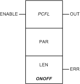
|
|
(Original Document)
|
|
Name in LL984 Editor
|
Function Block Name
|
|---|---|
|
name of legacy 984 instruction
|
name in other tools and editors like:
|
 |
 |
|
Configuration
|
If Input...
|
Then Output...
|
|---|---|---|
|
Direct
|
< (SP - DB)
|
ON
|
|
> (SP + DB)
|
OFF
|
|
|
Revers
|
> (SP + DB)
|
ON
|
|
< (SP - DB)
|
OFF
|

|
Input Pin
|
Name
|
Data Type
|
Address Range
|
Meaning
|
|---|---|---|---|---|
|
Top
|
ENABLE
|
–
|
ON = enables process control function
|
|
Node
|
Node Type
|
Name
|
Data Type
|
Address Range
|
Meaning
|
|---|---|---|---|---|---|
|
Middle
|
IN/OUT
|
PAR
|
ARRAY[1...14] OF UINT
|
%MW
|
see Parameter PAR below
|
|
Bottom
|
IN
|
LEN
|
UINT
|
14
|
length of parameter block (can not be changed)
|
|
Output Pin
|
Name
|
Data Type
|
Address Range
|
Meaning
|
|---|---|---|---|---|
|
Top
|
OUT
|
BOOL
|
–
|
ON = operation successful
|
|
Bottom
|
ERR
|
BOOL
|
–
|
ON = operation not successful
|
|
Word
|
Content
|
Format
|
|---|---|---|
|
1, 2
|
current input
|
REAL (Floating Point)
|
|
3
|
output status
|
UINT
|
|
4
|
input status
|
UINT
|
|
5, 6
|
set point, SP
|
REAL (Floating Point)
|
|
7, 8
|
deadband (DB) around set point
|
REAL (Floating Point)
|
|
9, 10
|
fully ON (maximum output)
|
REAL (Floating Point)
|
|
11, 12
|
fully OFF (minimum output)
|
REAL (Floating Point)
|
|
13, 14
|
output, ON or OFF
|
REAL (Floating Point)
|
|
Control Expert-IEC bits
|
Function
|
|---|---|
|
0...4
|
standard output bits (flags)
|
|
5
|
1 = output set to ON
0 = output set to OFF
|
|
6
|
echo mode:
1 = manual override
0 = auto mode
|
|
7
|
1 = DB set to negative number
|
|
8...15
|
not used
|
|
Control Expert-IEC bits
|
Function
|
|---|---|
|
0...8
|
not used
|
|
9
|
1 = force output ON in manual mode
0 = force output OFF in manual mode
|
|
10
|
1 = manual override
0 = auto mode
|
|
11
|
1 = reverse configuration
0 = direct configuration
|
|
12...15
|
standard input bits (flags)
|