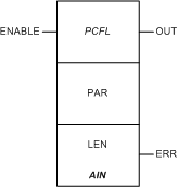
|
|
(Original Document)
|
|
Name in LL984 Editor
|
Function Block Name
|
|---|---|
|
name of legacy 984 instruction
|
name in other tools and editors like:
|
 |
 |

|
Input Pin
|
Name
|
Data Type
|
Address Range
|
Meaning
|
|---|---|---|---|---|
|
Top
|
ENABLE
|
ľ
|
ON = enables process control function
|
|
Node
|
Node Type
|
Name
|
Data Type
|
Address Range
|
Meaning
|
|---|---|---|---|---|---|
|
Middle
|
IN/OUT
|
PAR
|
ARRAY[1...14] OF UINT
|
%MW
|
see Parameter PAR below
|
|
Bottom
|
IN
|
LEN
|
UINT
|
1...14
|
length of parameter block (can not be changed)
|
|
Output Pin
|
Name
|
Data Type
|
Address Range
|
Meaning
|
|---|---|---|---|---|
|
Top
|
OUT
|
BOOL
|
ľ
|
ON = operation successful
|
|
Bottom
|
ERR
|
BOOL
|
ľ
|
ON = operation not successful
|
|
Word
|
Content
|
Format
|
|---|---|---|
|
1
|
input from a %MW address
|
UINT
|
|
2
|
reserved
|
UINT
|
|
3
|
output status
|
UINT
|
|
4
|
input status
|
UINT
|
|
5, 6
|
scale 100% (high) engineering units
|
REAL (Floating Point)
|
|
7, 8
|
scale 0% (low) engineering units
|
REAL (Floating Point)
|
|
9, 10
|
manual input
|
REAL (Floating Point)
|
|
11, 12
|
auto input
|
REAL (Floating Point)
|
|
13, 14
|
output
|
REAL (Floating Point)
|
|
Resolution
|
Range: Valid
|
Range: Under
|
Range: Over
|
|---|---|---|---|
|
+/-á10áV
|
768 ... 64 768
|
767
|
64 769
|
|
+/-á5áV
|
16 768 ... 48 768
|
16 767
|
48 769
|
|
0 ... 10áV
|
0 ... 64 000
|
0
|
64 001
|
|
0 ... 5áV
|
0 ... 32 000
|
0
|
32 001
|
|
1 ... 5áV
|
6 400 ... 32 000
|
6 399
|
32 001
|
|
Resolution
|
Range: Valid
|
|---|---|
|
TC degrees
|
-454 ... +3 308
|
|
TC 0.1 degrees
|
-4 540 ... +32 766
|
|
TC Raw Units
|
0 ... 65 535
|
|
Resolution
|
Range: Valid
|
Range: Under
|
Range: Over
|
|---|---|---|---|
|
+/-á10áV
|
-10 000 ... +10 000
|
-10 001
|
+10 001
|
|
+/-á5áV
|
-5 000 ... +5 000
|
-5 001
|
+5 001
|
|
0 ... 10áV
|
0 ... 10 000
|
0
|
10 001
|
|
0 ... 5áV
|
0 ... 5 000
|
0
|
5 001
|
|
1 ... 5áV
|
1 000 ... 5 000
|
999
|
5 001
|
|
ControláExpert-IEC bits
|
Function
|
|---|---|
|
0...4
|
standard output bits (flags)
|
|
5
|
1 = invalid engineering units
|
|
6
|
1 = invalid output mode selected
|
|
7
|
1 = echo over range from input module
|
|
8
|
1 = echo under range from input module
|
|
9
|
1 = input out of range
|
|
10
|
1 = with TC PSQRT, invalid: in extrapolation range, PSQRT not used
|
|
11...15
|
not used
|
|
ControláExpert-IEC bits
|
Function
|
|---|---|
|
0...4
|
not used
|
|
5
|
1 = extrapolate over-/under-range for auto mode
0 = clamp over-/under-range for auto mode
|
|
6
|
1 = manual scaling mode
0 = auto scaling mode
|
|
7
|
1 = process square root on raw input
|
|
8...12
|
Quantum Engineering Ranges (see following tables)
|
|
13...15
|
standard input bits (flags)
|
|
ControláExpert-IEC bits
|
|||||
|---|---|---|---|---|---|
|
Bitá12
|
Bitá11
|
Bitá10
|
Bitá9
|
Bitá8
|
Range
|
|
0
|
1
|
0
|
0
|
0
|
+/- 10áV
|
|
0
|
1
|
0
|
0
|
1
|
+/- 5áV
|
|
0
|
1
|
0
|
1
|
0
|
0 ... 10áV
|
|
0
|
1
|
0
|
1
|
1
|
0 ... 5áV
|
|
0
|
1
|
1
|
0
|
0
|
1 ... 5áV
|
|
ControláExpert-IEC bits
|
|
||||
|---|---|---|---|---|---|
|
Bitá12
|
Bitá11
|
Bitá10
|
Bitá9
|
Bitá8
|
Range
|
|
0
|
1
|
1
|
0
|
1
|
TC degrees
|
|
0
|
1
|
1
|
1
|
0
|
TC 0.1 degrees
|
|
0
|
1
|
1
|
1
|
1
|
TC raw units
|
|
ControláExpert-IEC bits
|
|
||||
|---|---|---|---|---|---|
|
Bitá12
|
Bitá11
|
Bitá10
|
Bitá9
|
Bitá8
|
Range
|
|
1
|
0
|
0
|
0
|
0
|
+/- 10áV
|
|
1
|
0
|
0
|
1
|
0
|
+/- 5áV
|
|
1
|
0
|
1
|
0
|
0
|
0 ... 10áV
|
|
1
|
0
|
1
|
1
|
0
|
0 ... 5áV
|
|
1
|
1
|
0
|
0
|
0
|
1 ... 5áV
|