Connecting the modules to ground (IP20)
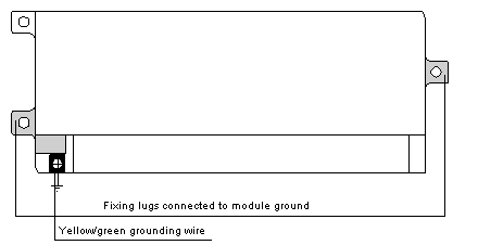
The fixing lugs for the monobloc or modular base units have a metallic plate connected to the functional ground of the module. This connection ensures the TBX modules function correctly provided modules are mounted on metal supports which are correctly connected to ground.
Basic modules and extension modules must be mounted on the same support or on supports which are correctly connected to each other.
The following drawing shows how to connect TBX IP20 modules to ground.
Connecting the modules to ground (IP65)
The TBX IP65 module is connected to ground using a TBX BLP 10 connector for the TBX EEP 08C22/EEP 1622 input modules.
This is done in the same way as for the TBX ESP 08C22/EEP 1622 output modules and via the grounding wire entering via the TBX BAS 10 connector which powers the preactuators.
Connecting the sensors and/or preactuators to ground (IP20).
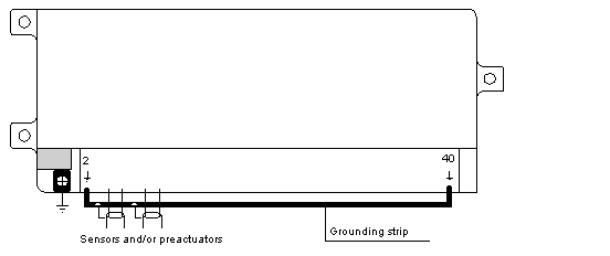
The grounding strip, reference TBX GND 015, is fixed to the ground terminals 2 and 40 of the module which allows the protective screening of the sensors and/or preactuators to be connected.
NOTE: it should be noted that this ground connection is not made when the terminal block is disconnected.
The following drawing shows how the sensors and/or preactuators (1P20) are grounded.
Connecting the sensors and/or preactuators to ground (IP65).
The sensors and preactuators (IP65) are connected to ground via terminal 5 of the M12 I/O connectors.
The terminals on TBX modules provide a cable size of:
-
1 x 1.5 mm2 maximum cable with cable end or 2.5 mm2 maximum (0.2 mm2 minimum) without cable end,
-
2 x 1 mm2 maximum flexible cable with cable end.
However, in order to make wiring easier and to increase accessibility, it is advisable to use a 1 mm2 flexible cable with a molded cable end (reference: DZ5-CE 010).

 DANGER