

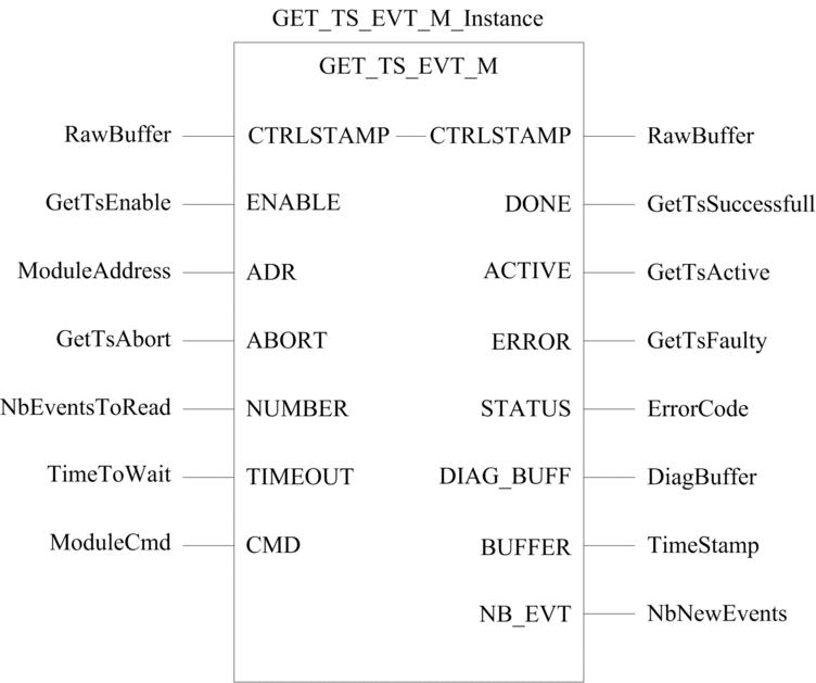
Description of the Function
The GET_TS_EVT_M function block
gets the time stamped data in:
BMX ERT 1604Twhen located in Modicon M340 local drop,BMX ERT 1604Twhen located in Modicon M580 local and remote drops,BME P58 xxxModicon M580 CPU,BMX CRA 312 10of a Modicon M580,BME CRA 312 10of a Modicon M580.
This function allows reading the event buffer to make it available for the PLC application.
The additional parameters EN and ENO can be configured.
FBD Representation
Representation:
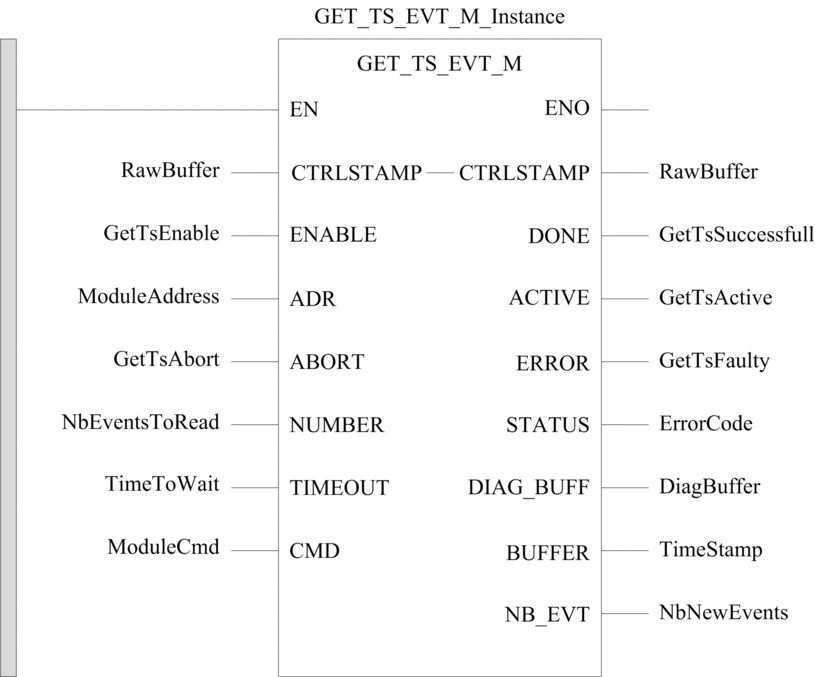
LD Representation
Representation:
IL Representation
Representation:
CAL GET_TS_EVT_M_Instance (CTRLSTAMP:=RawBuffer, ENABLE:=GetTsEnable,
ADR:=ModuleAddress, ABORT:=GetTsAbort, NUMBER:=NbEventsToRead, TIMEOUT:=TimeToWait,
CMD:=ModuleCmd, DONE=>GetTsSuccessfull, ACTIVE=>GetTsActive, ERROR=>GetTsFaulty,
STATUS=>ErrorCode, DIAG_BUFF=>DiagBuffer, BUFFER=>TimeStamp, NB_EVT=>NbNewEvents)
ST Representation
Representation:
GET_TS_EVT_M_Instance (CTRLSTAMP:=RawBuffer, ENABLE:=GetTsEnable,
ADR:=ModuleAddress, ABORT:=GetTsAbort, NUMBER:=NbEventsToRead, TIMEOUT:=TimeToWait,
CMD:=ModuleCmd, DONE=>GetTsSuccessfull, ACTIVE=>GetTsActive, ERROR=>GetTsFaulty,
STATUS=>ErrorCode, DIAG_BUFF=>DiagBuffer, BUFFER=>TimeStamp, NB_EVT=>NbNewEvents)
Description of the Parameters
The following table describes the input parameters:
Parameter |
Type |
Comment |
|---|---|---|
|
|
Set to 1 to send the request to the concerned module. |
|
|
Array containing the Modbus slave address, result of ADDM or ADDMX function. |
|
|
Set to 1 to abort the current operation. |
|
|
Maximum number of events to be read in the module local buffer. NOTE: Changing the
NUMBER value requires to set previously ENABLE to 0. |
|
|
Maximum time to wait for the drop reply. The time base for this parameter is 100 ms. NOTE:
TIMEOUT = 0 corresponds to an infinite waiting value. |
|
|
Set to:
|
The following table describes the output parameters:
Parameter |
Type |
Comment |
|---|---|---|
|
|
Function block completed indication. Set to 1 when the execution of the function block is completed successfully. |
|
|
Function block in progress indication. Set to 1 when the execution of the function block is in progress. |
|
|
Set to 1 if an error is detected by the function block. |
|
|
Code providing a communication and operation report.
|
|
|
Description:
|
|
|
Raw buffer containing event time stamp entries:
NOTE: The minimum
BUFFER size is 12 Words and should be a multiple of 6 otherwise error
16#0009 will be raised. |
|
|
Number of new events read in the BMX ERT 1604T local buffer. |
The following table describes the input/output parameters:
Parameter |
Type |
Comment |
|---|---|---|
|
|
Specifies the CPU raw record buffer:
|
STATUS Parameter
Description
The following table describes the STATUS parameter:
Communication Report (Byte 0) |
Operation Report (Byte 1) |
||
|---|---|---|---|
Value |
Description |
Value |
Description |
00 hex |
Correct exchange (request processed successfully) |
00 hex |
Positive result |
01 hex |
The number of events in the PLC buffer reaches the maximal value. |
||
02 hex |
The buffer is full and events have been overwritten since the last exchange. |
||
04 hex |
Buffer is full and the recording stops |
||
01 hex |
Exchange stop on timeout |
00 hex |
Default value |
02 hex |
Exchange stop on user request (CANCEL) |
00 hex |
Default value |
03 hex |
Incorrect address format |
00 hex |
Default value |
04 hex |
Incorrect destination address |
00 hex |
Default value |
06 hex |
Incorrect specific parameters |
01 hex |
Invalid |
02 hex |
User parameters have changed between 2 invocations while the EFB execution is active. |
||
07 hex |
Problem in sending to the destination |
00 hex |
Default value |
09 hex |
Insufficient receive buffer size (<1 EVT) or buffer size is not a multiple of 6 integers |
00 hex |
Default value |
0B hex |
No processor system resources |
00 hex |
Default value |
FF hex |
Incorrect exchange (request processed with failure) |
FF hex |
General communication error |
CTRLSTAMP Parameter
Description
CTRL_STAMP DDT structure example and link
with the PLC buffer:
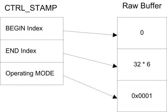
The example above shows the CTRL_STAMP content
after writing 32 events (1 event entry is 6 words long) in the PLC
buffer configured as follows:
PLC buffer is located and there are 32 events to write
Stop the recording when the buffer is full and continue with the previous value on power on.
Operating MODE word structure:
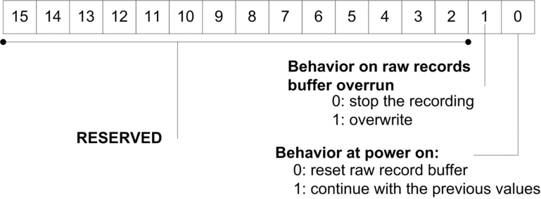
Buffer level:
If BEGIN Index = END Index then the buffer is empty
If END Index + 6 = BEGIN Index then the buffer is full (in the preceding equation, 6 represents the size of 1 event). The buffer is full when there is one space left for 1 event (6 x
INT).
EFB behavior on buffer full depends on the Operating
MODE parameter, bit 1 value:
If Behavior on raw records buffer overrun is set to 0 (stop the recording), the buffer is not filled with new data.
If Behavior on raw records buffer overrun is set to 1 (overwrite buffer), elder data or overwritten with newer data. In this case, the EFB updates both BEGIN Index and END Index.
Operating Mode of Enable, Active, Done and Error Parameters
The ENABLE, ACTIVE, DONE (or SUCCESS) and ERROR parameters operate as follows:
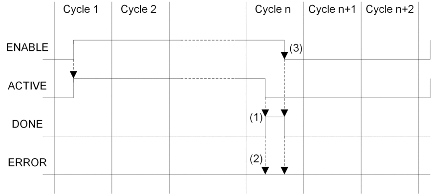
(1) DONE = 1 if no error, DONE = 0 if error
(2) ERROR = 0 if no error, ERROR = 1 if error
(3) If the ENABLE bit is reset to 0 before
completion, the function block is stopped (active bit to 0). To have
a complete block execution, the value of 1 must be applied on the
ENABLE bit until the operation has finished or until an error has
occurred.
The ENABLE parameter is written by the application.
The ACTIVE, DONE and ERROR parameters are read by the application.
To launch
the communication function only once, the ENABLE signal
needs to be reset to 0 once the ACTIVE parameter
is set to 0. If the ENABLE parameter is maintained
to 1 once the ACTIVE parameter is set to 0, the communication
function is launched again and the ACTIVE parameter
will be set to 1 on the next cycle.