Description of the Function

The R_NTPC function is available for M340, M580, Premium and Quantum PLCs. It is used to recover the date and time for an NTP server in two formats:

  • A display format.

  • A calculation format.

NOTE: This function requires connection to an Ethernet network enabling access to an NTP server.

The additional parameters EN and ENO can be configured.

FBD Representation

Representation:

LD Representation

Representation:
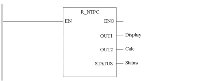
IL Representation

Representation:

R_NTPC(Display, Calc, Status)

ST Representation

Representation:

R_NTPC(Display, Calc, Status);

Description of the Parameters

The following table describes the output parameters:

Parameter

Type

Comment

Display

Display_NTPC

The Display output contains the date and time acquired on an NTP server. The Display_NTPC type is a predefined structure comprising a DT type element and an INT type element. This gives us:

  • Display.DT_value containing the date,

  • Display.Milisecond containing the number of milliseconds of this date, as the second is the minimum measurement unit for the DT format.

Calc

Calc_NTPC

The Calc output contains the date and time acquired on an NTP server (as in a Display variable, only with a different format). The Calc_NTPC type is a predefined structure comprising a UDINT type element and an INT type element. This gives us:

  • Calc.Seconds containing the number of seconds passed since January 1, 1980, at 00:00.

  • Calc.Fraction_Second containing the number of milliseconds to add for the precision of the result to be around a millisecond.

STATUS

INT

The low byte is managed by the CPU. When the low byte is set to 0:

  • the clock value is not available

  • the date and time are not updated within last two minutes

When the low byte is set to 1:

  • the date and time are updated within the last two minutes

  • the date and time are acceptable

If the processor is NTP client, the high byte is managed by the Ethernet module. When the high byte is set to 0, the clock value transferred to CPU is not acceptable.

When the high byte is set to 1, the updated date/time received from server and sent to module is:

  • within two minute time interval

  • acceptable (10 ms or less error)

For a valid time in CPU, the low and high bytes of the STATUS parameter must be set to 1. If not, it generates a Runtime error, see following explanation.

Runtime errors

If the low byte or the high byte of STATUS output is set to 0, the %S18 bit is set to 1 by the PLC system.