|
|
Original instructions
|
|
Stage
|
Description
|
|---|---|
|
1
|
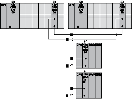
Assemble a Redundant Quantum RIO Network: Build a redundant Quantum network that includes Quantum S908 remote drops.
|
|
2
|
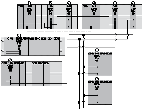
Assemble a Redundant Quantum EIO Network: Build a redundant Quantum network that includes both Quantum S908 remote drops and X80 remote drops.
|
|
3
|
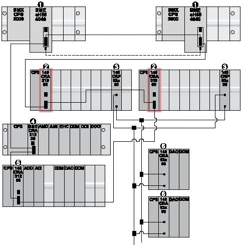
Complete the Migration: Replace the Quantum CPUs in the above example networks with 140CRA31908 adapter modules, and add redundant M580 CPUs in local racks.
|

1Quantum primary and standby CPUs on local racks with a fiber optic link
2140CRP93•00 communications modules with redundant connections to the Quantum S908 remote drops
3140CRA93•00 adapter module on a Quantum S908 remote drop
|
Step
|
Action
|
|---|---|
|
1
|
Add a 140CRP31200 communications module to each local rack in the redundant Quantum network.
|
|
2
|
Add an X80 remote drop with a Quantum adapter module to the main ring.
|
|
3
|
Add an X80 remote drop with an M580 adapter module to the main ring.
|
|
4
|
Build the Control Expert application and download it to the Quantum CPUs.
|

1Quantum primary and standby CPUs on local racks with a fiber optic link
2140CRP31200 communications modules
3140CRP93•00 adapter modules with redundant connections to the Quantum S908 remote drops
4BMECRA31200 adapter module on an X80 remote drop containing an M580 adapter module
5140CRA31200 adapter module on an X80 remote drop containing a Quantum adapter module
6140CRA93•00 adapter module on a Quantum S908 remote drop
|
Step
|
Action
|
|---|---|
|
1
|
Remove the Quantum CPUs from the racks in the order that is opposite to their installation.
|
|
2
|
Place the 140CRA31908 adapter modules in the slots from which you removed the CPUs.
|
|
3
|
Add redundant M580 CPUs in local racks.
NOTE: The configurations of the redundant M580 CPUs is identical. |
|
4
|
Connect the main ring to the M580 CPUs.
|
|
5
|
Remove the 140CRP31200 communications modules.
|
|
6
|
Modify your Control Expert application as necessary.
|
|
7
|
Download the Control Expert application to the M580 CPUs.
|

1M580 primary and standby CPUs on local racks with a fiber optic link
2140CRA31908 adapter modules
3140CRP93•00 communications modules
4BMECRA31200 adapter module on an X80 remote drop containing an M580 adapter module
5140CRA31200 adapter module on an X80 remote drop containing a Quantum adapter module
6140CRA93•00 adapter module on a Quantum S908 remote drop
|
System-driven switchover:
In a redundant 140CRA31908 module configuration, the CPU can drive a 140CRA31908 module switchover according to the status of both 140CRA31908 modules.
There is a case in which neither 140CRA31908 module can drive the I/O modules. When the master 140CRA31908 module loses communication with all Quantum S908 remote drops, the RIO status from the master 140CRA31908 module is unhealthy. Therefore, the standalone CPU or the primary CPU operates a 140CRA31908 module switchover and assigns the role of I/O master to the other 140CRA31908 module. If the new I/O master 140CRA31908 module cannot properly drive the I/O modules, it reports an unhealthy RIO status to the CPU. In that case, the CPU assigns the role of I/O master to the other 140CRA31908 module. The CPU repeats this loop until one of the two 140CRA31908 modules is able to drive the I/O modules.
|
|
Application-driven switchover:
You can use system bit %S88 to reassign the master of the I/O points. When %S88 is set, the system triggers a 140CRA31908 switch over and assigns the role of I/O master to the other 140CRA31908. The system then resets %S88.
NOTE: In redundant 140CRA31908 module configurations, check the status of the redundant 140CRA31908 module before a switchover is triggered. If the redundant 140CRA31908 module is not healthy, the system does not allow the switchover (even if %S88 is set). |