|


|
Original instructions
|
|
|
Original instructions
|

|
Title
|
Value scope
|
Default value
|
Description
|
|---|---|---|---|
|
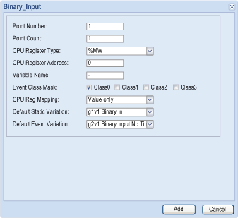
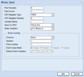
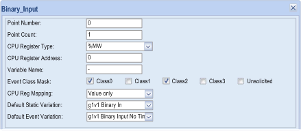
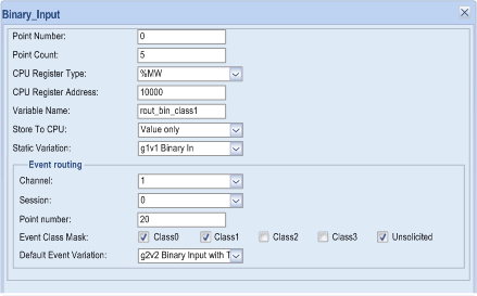
Point Number
|
0...16777215
|
0
|
indicates the start number of the point (1).
|
|
Point Count
|
1...65535
|
1
|
indicates the number of points.
|
|
CPU Register Type
|
%M/%MW/%S/%SW/ Unlocated
|
%MW
|
indicates the register type in CPU to map points (2).
|
|
CPU Register Address
|
0...30000
|
0
|
indicates start address of the register in CPU. This field only taken into account for located variables. With %S, the range is from 0 to 127.
|
|
Variable Name
|
–
|
–
|
indicates the variable name of the located or unlocated register.
|
|
Event Class Mask (0/1/2/3/Unsolicited)
|
check box
|
0
|
defines the event class of points. Unsolicited is not allowed with class 0 only. In client, Channel must be at 0.
|
|
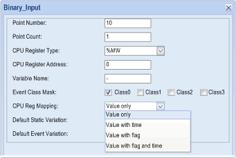
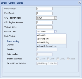
Store To CPU (Client) OR CPU Reg Mapping (Server)
|
Value only
Value with time
Value with flag
Value with flag and time
|
Value only
|
Event time stamp source:
Value only: module time
Value with time: time in CPU registers
Value with flag: flag info on the point is taken from CPU registers
Value with flag and time: flag and time are taken from CPU registers
|
|
(Default) Static Variation
|
g1v1 Binary In/ g1v2 Binary In Flag
|
g1v1 Binary In
|
indicates the default static variation for data point
|
|
Event routing (Client only)
|
|||
|
Channel
|
None/0
|
None
|
indicates the channel number to route
|
|
Session
|
0
|
0
|
indicates the session number to route (Channel at 0)
|
|
Point number
|
0...16777215
|
0
|
indicates the point number to route (Channel at 0)
|
|
Default Event Variation
|
g2v1 Binary Input No Time
g2v1 Binary Input With Time
g2v1 Binary Input Relative Time
|
g2v1 Binary Input No Time
|
indicates the default event variation for data point
|
1:The DNP3 point number must start from 0 and be contiguous in slave/server mode. If this is not applied, the nonconsecutive points cannot work normally. 2:DNP3 Server: %S applies only to binary inputs and %SW only to analog inputs, 32-bit analog inputs; the CPU mapping does not apply array due to the limits of Control Expert. |
|||
|
Point
|
Flag definition
|
Options
|
Comments
|
|---|---|---|---|
|
Binary Input Flags
|
on-line
|
bit 0: 0 (off-line)/ 1 (on-line)
|
–
|
|
restart
|
bit 1: 0 (normal/ 1 (restart)
|
||
|
communication lost
|
bit 2: 0 (normal/ 1 (lost)
|
||
|
remote forced data
|
bit 3: 0 (normal)/ 1 (forced)
|
||
|
local forced data
|
bit 4: 0 (normal)/ 1 (forced)
|
||
|
chatter filtered
|
bit 5: 0 (normal)/ 1 (filter on)
|
Events are generated when the CHATTER_FILTER flag is set and cleared, but not when CHATTER_FILTER is set.
|
|
|
reserved
|
bit 6: 0
|
Not used
|
|
|
state
|
bit 7: 0 /1
|
||
|
Binary Output Status Flags
|
on-line
|
bit 0: 0 (off-line)/1 (on-line)
|
–
|
|
restart
|
bit 1: 0 (normal/1 (restart)
|
||
|
communication lost
|
bit 2: 0 (normal/1 (lost)
|
||
|
remote forced data
|
bit 3: 0 (normal)/1 (forced)
|
||
|
local forced data
|
bit 4: 0 (normal)/1 (forced)
|
||
|
chatter filtered
|
bit 5: 0
|
Not used
–
|
|
|
reserved
|
bit 6: 0
|
||
|
state
|
bit 7: 0 /1
|
||
|
Double Input Flags
|
on-line
|
bit 0: 0 (off-line)/1 (on-line)
|
–
|
|
restart
|
bit 1: 0 (normal/1 (restart)
|
||
|
communication lost
|
bit 2: 0 (normal/1 (lost)
|
||
|
remote forced data
|
bit 3: 0 (normal)/1 (forced)
|
||
|
local forced data
|
bit 4: 0 (normal)/1 (forced)
|
||
|
chatter filtered
|
bit 5: 0 (normal)/1 (filter on)
|
Events are generated when CHATTER_FILTER flag is set and cleared, but not when it is set.
|
|
|
state
|
bit 6: 0/1
|
Not used
|
|
|
state
|
bit 7: 0/1
|
||
|
Analog Input Flags
|
on-line
|
bit 0: 0 (off-line)/1 (on-line)
|
–
|
|
restart
|
bit 1: 0 (normal/1 (restart)
|
||
|
communication lost
|
bit 2: 0 (normal/1 (lost)
|
||
|
remote forced data
|
bit 3: 0 (normal)/1 (forced)
|
||
|
local forced data
|
bit 4: 0 (normal)/1 (forced)
|
||
|
over range
|
bit 5: 0 (normal)/1 (over range)
|
||
|
reference error
|
bit 6: 0 (normal)/1 (error)
|
||
|
reserved
|
bit 7: 0
|
Not used
|
|
|
Analog Output Status Flags
|
on-line
|
bit 0: 0 (off-line)/1 (on-line)
|
–
|
|
restart
|
bit 1: 0 (normal/1 (restart)
|
||
|
communication lost
|
bit 2: 0 (normal/1 (lost)
|
||
|
remote forced data
|
bit 3: 0 (normal)/1 (forced)
|
||
|
local forced data
|
bit 4: 0 (normal)/1 (forced)
|
||
|
over range
|
bit 5: 0 (normal)/1 (over range)
|
||
|
reference error
|
bit 6: 0 (normal)/1 (error)
|
||
|
reserved
|
bit 7: 0
|
Not used
|
|
|
Counter Flags
|
on-line
|
bit 0: 0 (off-line)/1 (on-line)
|
–
|
|
restart
|
bit 1: 0 (normal/1 (restart)
|
||
|
communication lost
|
bit 2: 0 (normal/1 (lost)
|
||
|
remote forced data
|
bit 3: 0 (normal)/1 (forced)
|
||
|
local forced data
|
bit 4: 0 (normal)/1 (forced)
|
||
|
roll over
|
bit 5: 0
|
Not used
|
|
|
discontinuity
|
bit 6: 0 (normal)/1 (discontinuity)
|
–
|
|
|
reserved
|
bit 7: 0
|
Not used
|
|
TCC (Trip-Close Code)
|
Operation type field
|
Control code
|
Point model in outstation
|
|---|---|---|---|
|
None
|
pulse on
|
01 hex
|
activation
|
|
latch on
|
03 hex
|
latch complement
|
|
|
latch off
|
04 hex
|
||
|
Close
|
pulse on
|
41 hex
|
two’s complement
|
|
Trip
|
81 hex
|
|
CROB sent in DNP3 master
|
Point number in DNP3 master
|
Point number in DNP3 slave
|
|---|---|---|
|
Pulse on
|
0
|
0
|
|
Trip/Pulse on
|
0
|
1
|
|
Close/Pulse on
|
2
|
2
|
|
Trip/Pulse on
|
2
|
3
|
|
Close/Pulse on
|
n+2
|
n+2
|
|
Trip/Pulse on
|
n+2
|
n+2+1
|
|
Op type field
|
Trigger mechanism
|
Description
|
|---|---|---|
|
Close/Pulse_on
|
any value change (0...65535)
|
pulse on if value change
|
|
Latch_on
|
0 to 1
|
latch on
|
|
Latch off
|
1 to 0
|
latch off
|
|
Close/Pulse_on
|
0 to 1
|
pulse on for close output
|
|
Trip/Pulse_on
|
1 to 0
|
pulse on for trip output
|

|
Parameter
|
Value Scope
|
Default Value
|
Definition
|
|---|---|---|---|
|
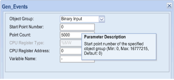
Object Group
|
Binary Input
Double Input
Binary Counter
Analog Input
Binary Output
Analog Output
|
Binary Input
|
specifies the object group whose event must be generated on demand
|
|
Start Point Number
|
0..16777215
|
0
|
specifies the start point number of the specified object group
|
|
Point Count
|
1...5000
|
5000
|
specifies the point number to generate events
5000: the actual count depends on the point number of the object group’s configuration)
|
|
CPU Register Type
|
%MW
|
%MW
|
indicates the register type in the CPU to map points to; only the %MW type is supported
|
|
CPU Register Address
|
0...32464
|
0
|
indicates the start address of the register in the CPU. Effective for the located variables only
|
|
Variable Name
|
–
|
–
|
indicates the name of the located register
|
|
Parameter
|
Value Scope
|
Default Value
|
Definition
|
|---|---|---|---|
|
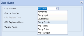
Object Group
|
All Objects
Binary Input
Double Input
Binary Counter
Analog Input
Binary Output
Analog Output
|
All Objects
|
specifies the object group whose event must be cleared on demand
|
|
Channel Number
|
0..255
|
255 (all the channels)
|
specifies the channel number to clear (it depends on channel configuration)
|
|
CPU Register Type
|
%MW
|
%MW
|
indicates the register type in the CPU to map points to; only the %MW type is supported
|
|
CPU Register Address
|
0...32464
|
0
|
indicates the start address of the register in the CPU. Effective for the located variables only
|
|
Variable Name
|
–
|
–
|
indicates the name of the located register
|
