Introduction
The order of execution in networks and the execution order of objects within a network are defined by a number of rules.
In some cases the execution order suggested by the system should be changed.
The procedure for defining/changing the execution sequence of networks is as follows:
Using Links Instead of Actual Parameters
Network Positions
The procedure for defining/changing the execution sequence of networks is as follows:
Positioning of Objects
Original Situation
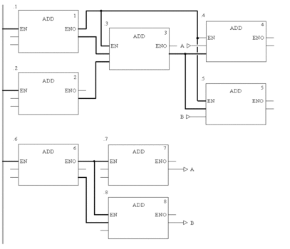
The following representation shows two networks for which
the execution sequences are only defined by their position within
the section, without taking into account that block 0.4/0.5 and 0.7/0.8 require another execution sequence.
Link Instead of Actual Parameter
By using a link instead of a variable the two networks are run in the proper sequence (see also Original Situation).
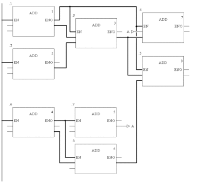
Network Positions
The correct execution sequence can be achieved by changing the position of the networks in the section (see also Original Situation).
Positioning of Objects
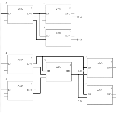
The position of objects can only have an influence on the execution order if several inputs (left link of Contacts/Coils, FFB inputs) are linked with the same output of the object "to be called" (right link of Contacts/Coils, FFB outputs) (see also Original Situation).
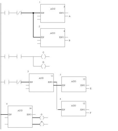
Original situation:
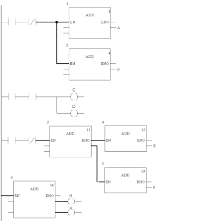
In the first network, block positions 0.1 and 0.2 are switched. In this case (common origins
for both block inputs) the execution sequence of both blocks is switched
as well (processed from top to bottom). The same applies when switching
coils C and D in the second network.
In the third network, block positions 0.4 and 0.5 are switched. In this case (different origins
for the block inputs) the execution sequence of the blocks is not
switched (processed in the sequence that the block outputs are called
in). The same applies when switching coils G and H in the last network.
