At a Glance
The DDTs are stored in the memory of the PLC in the order in which its elements are declared.
However, the following rules apply.
Principle for Premium and Quantum
The storage principle for Premium and Quantum is as follows:
the elements are stored in the order in which they are declared in the structure,
the basic element is the byte (alignment of data on the memory bytes),
each element has an alignment rule:
the
BOOLandBYTEtypes are indiscriminately aligned on the odd or even bytes,all the other elementary types are aligned on the even bytes,
the structures and tables are aligned according to the alignment rule for the
BOOLandBYTEtypes if they only containBOOLandBYTEelements, otherwise they are aligned on the memory's even bytes.
| WARNING | |
|---|---|
Principle for Modicon M340, M580, and Momentum
The storage principle for these PLCs is as follows:
elements are stored in the order in which they are declared in the structure,
the basic element is the byte,
one alignment rule and function of the element:
the
BOOLandBYTEtypes are aligned on either even or uneven bytes,the
INT,WORDandUINTtypes are aligned on even bytes,the
DINT,UDINT,REAL,TIME,DATE,TOD,DTandDWORDare aligned on double words,structures and tables are aligned according to the rules of their elements.
| WARNING | |
|---|---|
Modicon M580 Device DDT Alignment for I/O Scanning
Two modes of I/O scanning are proposed:
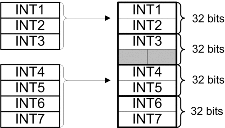
Legacy I/O scanning mode (used in Unity Pro ≤ V11.1) creates Device DDT structures aligned on 32 bits by default.
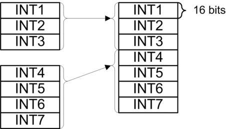
Enhanced I/O scanning mode (compatible for applications created with Unity Pro ≥ V12.0) creates Device DDT structures aligned on 16 bits by default.
Unity Pro is the former name of Control Expert for version 13.1 or earlier.
To keep the original alignment for applications created for Unity Pro ≤ V11.1, select the legacy I/O scanning mode.
Alignment mismatch illustration for Modbus TCP device:
Example of arrangement in legacy mode (32 bits alignment, array of 4 x
BYTE). When 3INTare transmitted, the structure in legacy mode creates 2 empty bytes that need to be considered in the global structure interpretation.
Example of arrangement in enhanced mode (16 bits alignment, array of
INT). When 3INTare transmitted, no empty bytes are added by the system, all the data in the structure are useful.
Examples
The following
table gives some examples of data structures. In the following examples,
structure type DDTs are addressed to %MWi. The word’s
first byte corresponds to the least significant 8 bits and the word’s
second byte corresponds to the most significant 8 bits.
For
all the following structures, the first variable is mapped to the
address %MW100:
First Memory Address |
Description of the structure |
||
|---|---|---|---|
Modicon M340, M580 or Momentum |
Premium |
Para_PWM1 |
|
|
|
t_period: TIME |
|
|
|
t_min: TIME |
|
|
|
in_max: REAL |
|
Mode_TOTALIZER |
|||
|
|
hold: BOOL |
|
|
|
rst: BOOL |
|
Info_TOTALIZER |
|||
|
|
outc: REAL |
|
|
|
cter: UINT |
|
|
|
done: BOOL |
|
|
|
Reserved for the alignment |
|
The table below gives two examples of data structures with arrays:
First Memory Address |
Description of the structure |
||
|---|---|---|---|
Modicon M340, M580 or Momentum |
Premium |
EHC105_Out |
|
|
|
Quit: BYTE |
|
|
|
Control: ARRAY [1..5] OF BYTE |
|
|
|
Final: ARRAY [1..5] OF DINT |
|
CPCfg_ex |
|||
|
|
Profile_type: INT |
|
|
|
Interp_type: INT |
|
|
|
Nb_of_coords: INT |
|
|
|
Nb_of_points: INT |
|
|
|
reserved: ARRAY [0..4] OF BYTE |
|
|
|
Reserved for the alignment of variable Master_offset on even bytes |
|
|
|
Master_offset: DINT |
|
|
|
Follower_offset: INT |
|
|
- |
Reserved for the alignment |
|


