Description
TIMER-type event processing is any process triggered by the ITCNTRL function.
This timer function periodically activates event processing every time the preset value is reached.
Reference
The following parameters are selected in the event processing properties.
Parameter |
Value |
Default value |
Role |
|---|---|---|---|
Time base |
1 ms, 10ms, 100ms, 1 sec |
10ms |
Timer time base. Note: the time base of 1ms should be used with care, as there is a risk of overrun if the processing triggering frequency is too high. |
Preset |
1..1023 |
10 |
Timer preset value. The time period obtained equals: Preset x Time Base. |
Phase |
0..1023 |
0 |
The value of the temporal offset between the STOP/RUN transition of the PLC and the first restart of the timer from 0. The temporal value equals: Phase x Time Base. |
ITCNTRL Function
Representation in FBD:

The following table describes the input parameters:
Parameter |
Type |
Comment |
|---|---|---|
|
BOOL |
Enable input selected |
|
BOOL |
At 1 resets the timer |
|
BOOL |
At 1, freezes timer incrementation. |
|
BYTE |
Input byte which determines the event processing number to be triggered. |
The following table describes the output parameters:
Parameter |
Type |
Comment |
|---|---|---|
|
WORD |
Status word. |
|
TIME |
Current value of timer. |
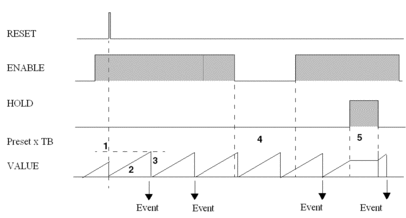
Timing Diagram for Normal Operation
Timing diagram.

Normal operation
The following table describes the triggering of TIMER-type event processing operations (see timing diagram above).
Phase |
Description |
|---|---|
1 |
When a rising edge is received
on the |
2 |
The current value |
3 |
An event is generated when the current value has reached the preset value, the timer is reset to 0, and then reactivated. The associated event processing is also triggered, if the event is not masked. It can be deferred if an event processing task with a higher or identical priority is already in progress. |
4 |
When the |
5 |
When the |
Event Processing Synchronization
The Phase parameter is used to trigger different TIMER-type event processing tasks at constant time intervals.
This parameter set a temporal offset value with an absolute time origin, which is the last passage of the PLC from STOP to RUN.
Operating condition:
The event processing tasks must have the same time base and preset values.
The
RESETandHOLDinputs must not be set to 1.
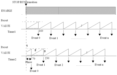
Example: Two event processing tasks Timer1 and Timer2 to be executed at 70ms interval.
Timer1 can be defined with a phase equal to 0 and the second Timer2 with a phase of 70ms (phase of 7 and time base of 10ms).
Any event triggered by the timer associated with the Timer1 processing task shall be followed after an interval of 70ms by an event from the timer associated with the Timer2 processing task
Timing Diagram: STOP/RUN Transition
Timing diagram of the example provided above with the same preset value of 16 (160ms) for Timer1 and Timer2.

Operation After PLC STOP/RUN
The following table describes the operation of the PLC after a transition from STOP into RUN (see timing diagram above):
Phase |
Description |
|---|---|
1 |
ON a STOP RUN transition of the PLC, timing is triggered so that the preset value is reached at the end of a time period equal to Phase x time base, when the first event is sent out. |
2 |
The current value |
3 |
An event is generated when the current value has reached the preset value, the timer is reset to 0, and then reactivated. The associated event processing is also triggered, if the event is not masked. If can be deferred, if there is an event processing task of higher or identical priority already in progress. |


