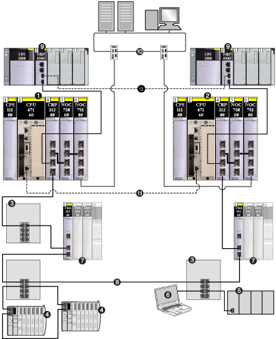
Local Slave Networking Example
The Ethernet communication module supports up to 3 instances of the local slave functionality. The local slave functionality allows other scanners on the network to read from, and write to, the Ethernet communication module using implicit messaging. Each local slave instance can accept one exclusive owner connection and one listen only connection. Through a local slave, a remote scanner can access the communication module’s
CIP assembly object. The local slave function is especially beneficial for peer-to-peer data exchanges at a repetitive rate.
NOTE:
-
The Ethernet communication module can provide 3 local slave adapter instances, while simultaneously performing as a scanner. These roles are not mutually exclusive.
-
The local slave is exclusively an EtherNet/IP functionality.
In the following example, the local slave instance is part of the following topology:
1
primary PLC (containing remote I/O, distributed I/O, and control head modules)
2
standby PLC
3
DRS connecting remote I/O and distributed I/O devices to the main ring
4
distributed I/O device (Advantys STB island)
5
third-party PLC
6
PC
7
remote I/O devices
8
main ring
9
Modicon X80 racks — connected to the PLCs via copper cable — containing BMX NRP 020• fiber converter modules to extend the distance between the 2 PLCs beyond 100 m
10
control network (connected to the primary and standby PLCs)
11
CPU-sync link (fiber cable)
12
fiber cable connecting the two BMX NRP 020• modules to extend the distance between the 2 PLCs beyond 100 m
This sample configuration includes the following devices:
-
A primary PLC (1) incorporates the 140NOC78000 head module with one local slave instance enabled. The PLC scans I/O data from remote devices (4).
-
A standby PLC (2) listens to the scan of the primary PLC’s local slave by the third-party PLC (5).
-
(3)
-
An Advantys STB island (4) includes an STB NIC 2212 network interface module plus 8 I/O modules.
-
A third-party scanner (5) lacks adapter capability and therefore cannot itself be scanned by the primary PLC:
-
The scanner collects data from sources that are not part of this network.
-
The scanner writes data to inputs of the primary PLC’s local slave.
-
The scanner scans the primary PLC’s local slave’s output data through an exclusive owner connection.
-
A PC (6) runs this software:
NOTE:
-
Because the third-party scanner (5) and the standby scanner (2) both receive the same data from the local slave, confirm that the requested packet interval () settings of the third-party scanner’s exclusive owner connection and the standby scanner’s listen-only connection are the same.
-
By enabling a local slave on the primary PLC (1):
-
The PLC (1) allows the third-party PLC (5) to write to it at a repetitive rate, even if the PLC is not capable of acting as an adapter.
-
The standby PLC (2) is able to scan the primary PLC (1) at a repetitive rate, rather than through application-intensive explicit messaging.
The following topics show you how to use Control Expert software installed in the PC (6) to configure a local slave, and to create input and output items in support of the peer-to-peer data transfers between and among scanners.
