|
Ethernet Configuration Tool User Interface
|
|
|
Original instructions
|
|
When a device and its DTM are...
|
You can use the Ethernet configuration tool to...
|
|---|---|
|
Connected
|
Monitor and diagnose the real-time operation of the device or module
|
|
Disconnected
|
Configure a communication module or remote device by editing its properties
|
|
Step
|
Action
|
|---|---|
|
1
|
In the DTM Browser select the DTM that you want to connect to, or disconnect from, the physical communication module or remote device.
NOTE: If the module or device name appears in:
|
|
2
|
Click the right mouse button. A pop-up menu opens.
|
|
3
|
Select one of the following commands:
NOTE: The Connect and Disconnect commands are also available in the Control Expert Edit menu. |
|
When the communication module and its DTM are...
|
The Device Editor opens in this mode...
|
|---|---|
|
Connected
|
read / write
|
|
Disconnected
|
read-only
|

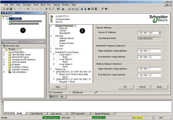
1DTM Browser
2Device Editor
|
Step
|
Action
|
|---|---|
|
1
|
(if necessary) In the DTM Browser, select the Ethernet communication module node and click the right mouse button. then select Disconnect in the pop-up menu.
|
|
2
|
In the DTM Browser, again select the Ethernet communication module node and click the right mouse button. The same pop-up menu opens.
|
|
3
|
Select Device menu → Configuration in the pop-up menu. The Device Editor opens.
|

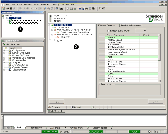
1DTM Browser
2Diagnostic Window
|
Step
|
Action
|
|---|---|
|
1
|
(if necessary) In the DTM Browser, select the Ethernet communication module node and click the right mouse button, then select Connect in the pop-up menu.
|
|
2
|
In the DTM Browser, again select the Ethernet communication module node and click the right mouse button. The same pop-up menu opens.
|
|
3
|
Select Device menu → Diagnostics in the pop-up menu. The Diagnostic Window opens.
|