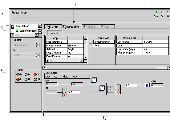
In Online mode, process control debugging screens are used to:
-
display and animate the loop diagram
-
display process alarms and channel faults
-
modify adjustment parameters for each function
-
simulate input interface values
-
add, delete, and replace calculation functions
-
modify configuration parameters of each PID reverse/forward mode-type function
-
modify loop controller operating modes
The following figure shows a debugging screen.
The following table describes the main components of the Process Control Debugging screen, as well as their respective function.
|
Address
|
Component
|
Function
|
|
1
|
Tabs
|
The foremost tab indicates the current mode (Debug, in this instance). Select each mode by clicking on the corresponding tab. The following modes are available:
-
Configuration,
-
Debugging, accessible only in Online mode,
-
WARNING displays warning messages pertaining to the process control loop status,
-
Diagnostics, (Default) accessible only in Online mode.
|
|
2
|
Module area
|
Displays the abridged module indicator.
There are three indicators in the same zone that provide the status of the PLC in online:
-
RUN indicates the status of the PLC,
-
ERR indicates a fault on the processor or embedded devices.
-
I/O indicates a fault from a module, channel or configuration.
|
|
3
|
Channel area
|
Is used:
-
By clicking on the reference number, to display the tabs:
-
To select the loop controller,
-
To display the Symbol, name of the channel defined by the user (using the variable editor).
|
|
4
|
Global Parameters area
|
Lists the general settings (or parameters) associated to the channel :
-
Function: Process Control function associated to the loop. This parameter is invariable.
-
Task: defines the MAST or FAST task through which the channel's implicit exchange objects will be exchanged. This parameter is invariable.
The Alarms area. If the alarm functions are defined, displays all loop-associated alarms.
|
|
5
|
Debug area
|
Allows viewing of configured functions and block diagram.
This area comprises two sections:
-
The block diagram shows the intermediary calculation values (loop controller input measurement, for example).
Click once on the mouse button to make changes to Auto/Manu and Remote/Local settings.
Associated command values or setpoint values are captured directly in the input fields.
Grayed-out input fields are inactive.
|
