Debugging a Feed forward branch requires Leadlag adjustment The following procedure and example describe the procedure to be respected.
This table describes the steps required in order to adjust the Leadlag of a Feed forward branch.
|
Step
|
Action
|
|
1
|
Put the loop controller into manual mode.
|
|
2
|
Position T1_FF at the time constant value for the process.
|
|
3
|
Position T2_FF at the time constant value for the disruption.
|
|
4
|
Carry out a disruption grade:
-
if the overshoot is positive, reduce T1_FF, and similarly, if the overshoot is negative, increase T1_FF
-
if the overshoot starts positively, increase T2_FF, and similarly, if the overshoot starts negatively, reduce T2_FF
|
|
5
|
Repeat step 4 until the overshoot is cancelled out.
|
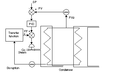
Example of Leadlag Adjustment
An adjustment of the PV2 output temperature on the secondary circuit of the exchanger is required. A PID controls the incoming hot air valve according to PV2 and the SP setpoint. The cold water temperature acts as a measurable disruption in relation to this process control.
The Feed forward function can be used to react as soon as the cold water temperature fluctuates and not if PV2 has decreased.
Illustration of the example:
The working hypotheses are as follows:
-
The output temperature of the condenser (temperature of the cold water) fluctuates between 5 and 25 degrees Celsius, with an average value of 15 degrees.
-
A DT variation in this temperature affects the exchanger output temperature entirely.
-
In order to compensate for an increase or decrease of 5 degrees Celsius in the exchanger output temperature, the controlling steam valve must be opened or closed by 10%.
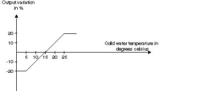
Adjustments to the Feed forward input parameters must be such that the contribution of the cold water temperature to the valve controlling the steam flow rate is:
The following figure illustrates the adjustment.