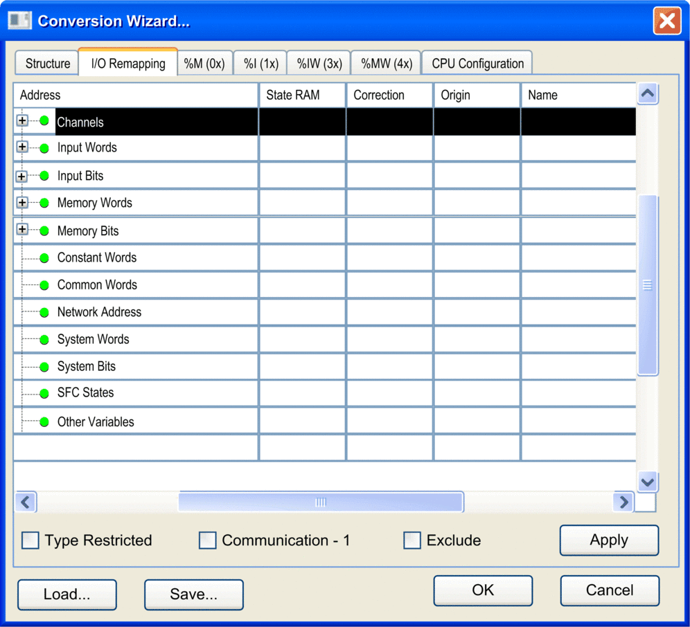
Overview
The remapping table shows all variables with direct addresses used in the application whether they are declared or not.
Even if directly addressed variables appear only in programs, they are detected and displayed in this table.
Representation
tab

Elements of the Remapping Table
To see all columns of the table scroll horizontally.
Element |
Description |
|---|---|
|
Topological or direct variable address For detailed information please refer to paragraph below. |
|
This column is only available for Concept, Modsoft, ProWORX32 or ProWORX Nxt applications with State RAM assignments. If the column is visible, the column only accepts State RAM addresses. |
|
In this column you can enter corrections for the values of the column. Use the same format as in column. Example: |
|
Source module of the imported legacy application |
|
A comma-separated list of section names in which the variable is used or the description of the hardware module, if available in the application file. |
|
Symbolic name |
|
Variable type |
|
Variable comment |
|
Starts the defined remapping for the currently selected variables. |
|
Please refer toExclude, Communication -1, Type Restriction. |
|
|
|
Address
For data that have hierarchical elements, like channels for hardware modules in TSX Premium and TSX Micro, there is an extension sign (+) to expand the list. For example, an overview of the channels of the hardware modules is displayed.
The column shows the hierarchy of the topological addresses
in tree form. The rows are sorted according to the module addresses
(e.g. %CH0.1*), which are shown as:
%CH{\<Bus alias>.<Connection point>\}<Rack>.<Module>.*
The module addresses are derived from the hardware modules present in the configuration part of the application file.
The
addresses are composed with a wildcard character ".*". The wildcard character stands for all channels of the hardware
module (e.g. %CH0.1*).
In the next level (e.g. %CH0.6.1.*), that can be expanded by clicking the extension
sign (+) in front of a module row, the channels of the module are
listed.
This is done by additionally showing the channel number,
followed by a wildcard character ".*". The wildcard
character stands here for the various data of the channel, which can
have more than 1 level.
Below the item, there are the items for and that are both subdivided into and . These 4 groups directly represent the State RAM of the PLC. They only show those variables that are used in the entire program. Unused I/O variables are not displayed here.
The 2 groups contain clusters of memory items with consecutive addresses. In these groups it is allowed to rearrange consecutive areas. This is not allowed in the 2 groups.
Correction
You can define new start addresses for the memory items in the and groups. The new addresses are displayed in the column of the tab. For further information on the remapping process, refer to the chapter Clustering and Remapping of Memory Variables.
Section
The column shows a comma-separated list of section names in which the variable is used or the description of the hardware module, if available in the application file.


