Introduction
Coils can be placed in any free cell except cells directly on the left power rail.
If all coils are to be placed on the right power rail, select the menu, and in the tab, check the checkbox.
If a coil is placed in a cell that is already occupied by a Boolean link or a label, the cell contents are replaced by the new coil.
If a coil is placed in a cell that is already occupied by a coil, or a contact, a confirmation message is returned to replace the cell contents by the new coil.
If a coil is placed in a cell that is already occupied by another object and can not be replaced (e.g. FFBs), an error message is returned
A placed coil automatically creates a connection with its neighboring
objects on the left and right if they are of the BOOL data type, even if free cells are between them.
The following are permitted as actual parameters for coils:
Boolean variables
Boolean addresses (topological addresses or symbolic addresses)
Note
In the dialog box on the tab, if the checkbox is selected, then the corresponding properties dialog box is automatically opened when an object is placed. The procedures explained here are used when the checkbox is cleared.
Placing Coils
Placing Coils
Step |
Action |
|---|---|
1 |
Select the desired coil. |
2 |
Click the target cell in the LD section. or Use the arrow keys to move the gray field to the target position, and press Enter. Result: The selected coil is inserted. In the dialog box, on the tab, if the checkbox is selected and the last cell in the current row (cell directly on the right power rail) is not occupied, the coil is placed automatically on the right power rail. If this cell is already occupied, the coil is inserted into the current cell (cursor position gray field). |
3 |
To place further coils of the same type:
|

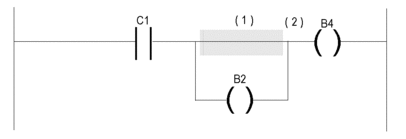
If the short-circuit (1) is located on top of the coil B2, this coil will remain in a true state (B2 = 1) regardless of the logic activating the coil C1. As a consequence, the active state (2) is propagated to the following logic (b4 = 1).
Assigning actual parameters
Assigning actual parameters:
Step |
Action |
|---|---|
1 |
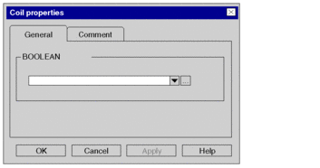
Open the properties dialog box for the coil. Result: The coils properties dialog box is opened. Example:  |
2 |
You have the following options to enter the actual parameters:
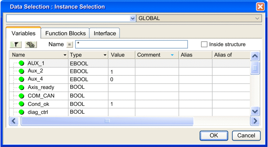
Example of a variable selection dialog box:  |
3 |
Confirm the selected variable with . Result:
|
4 |
If you do not want to assign the
variable an address or comment, confirm using Enter or the Result:The variable is declared and enabled in the section. A syntax and semantics check is performed and the procedure ends here. Example:  |
5 |
If you do want to assign the variable
an address and/or comment, use the  |
6 |
Confirm with Enter or the Result:The variable is declared and enabled in the section. A syntax and semantics check is performed. Example:  |
Calling a subroutine
Calling a subroutine:
Step |
Action |
|---|---|
1 |
Place a call coil in the section. Note: Subroutine calls are expansions to IEC 61131-3 and must be explicitly enabled via the dialog box, in the tab by selecting the checkbox. |
2 |
Open the properties dialog box for the coil. Result: The coils properties dialog box is opened. |
3 |
Click the Note: The subroutine to be called must be located in the same task as the LD section called. Result: The subroutine call is inserted into the section and a syntax and semantics check is performed. Example:  If the subroutine has already been created, the procedure ends here. If the subroutine has not yet been created, continue with step 4. |
4 |
Create the subroutine. |


 symbol and confirm using Enter.

 symbol. In this case, the
variable name is enabled in the section, but not declared.
 symbol.
 symbol for obtaining an advanced dialog and
enter the address and/or comment.
 symbol.
 symbol and select the subroutine to call from
the list and confirm using Enter.