Introduction
The configuration tool is used to:
create\modify\save the elements involved in the configuration of the PLC station,
set up the application-specific modules comprising the station,
diagnose the modules configured in the station,
assess the current discharged from the voltages supplied by the power supply module declared in the configuration,
control the number of application-specific channels configured in relation to the capacities of the processor declared in the configuration.
assess the processor memory usage.
The configuration may be performed before or after the programming of the project; this has the advantage of being able to create generic projects without having to be concerned with the configuration in the initial stage.
The various services are provided through 2 editors which are:
the bus editor, which allows you to select and position the modules or devices on the bus,
the input/output module editor, which allows you to set up the modules or devices present on the PLC station bus(es).
| CAUTION | |
|---|---|
At a Glance
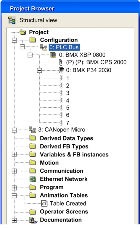
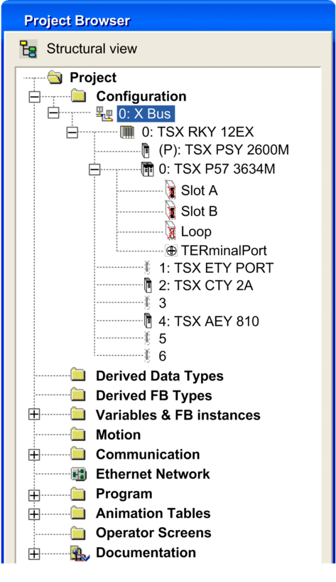
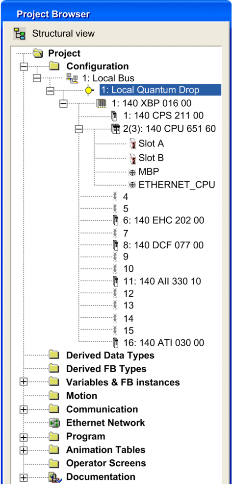
From the project browser, you can view the hardware configuration of the PLC station by opening the Configuration directory.
The hardware configuration of the station is displayed in a directory tree.
Configuration example for a Modicon M340 station:

Configuration example for a Premium station:

Configuration example for a Quantum station:


