BME P58 xxxx Module View
CPU front view:
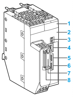
1 LED display
2 MAC address
3 mini-B USB connector
4 SERVICE port
5 DEVICE NETWORK port
5 DEVICE NETWORK port
5 SD memory card slot
5 SD status LED
LED display:
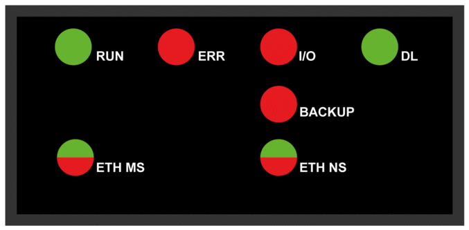
The following table describes the LED indicator patterns:
Symbol |
Description |
Symbol |
Description |
|---|---|---|---|
 |
off |
 |
steady red |
 |
steady green |
 |
blinking red |
 |
blinking green |
 |
blinking red/green |
The following table describes the LED display activity meaning for diagnostic purpose:
Condition |
CPU State |
RUN |
ERR |
I/O |
ETH MS |
ETH NS |
|---|---|---|---|---|---|---|
power on |
Autotest |
 |
 |
 |
 |
 |
not configured (before getting a valid IP address or configuration is invalid) |
NOCONF |
 |
 |
 |
 |
any pattern |
configured |
Stop |
 |
 |
• off: no error detected • steady red: error detected in a module or a channel |
 |
• off: invalid IP address • steady red: duplicate IP address • blinking green: valid IP address but no EtherNet/IP connection • steady green: EtherNet/IP connection established |
RUN |
 |
 |
 |
|||
recoverable detected error |
HALT |
 |
 |
any pattern |
 |
• steady red: duplicate IP address • blinking red: At least one exclusive owner CIP connection (for which the BME NOC 03•1 is the originator) is timed out. The LED blinks until the connection is reestablished or the module is reset. |
unrecoverable detected error |
– |
 |
 |
 |
 |
 |
power off |
– |
 |
 |
 |
 |
 |
BMX ERT 1604 T Module View
Module front view:
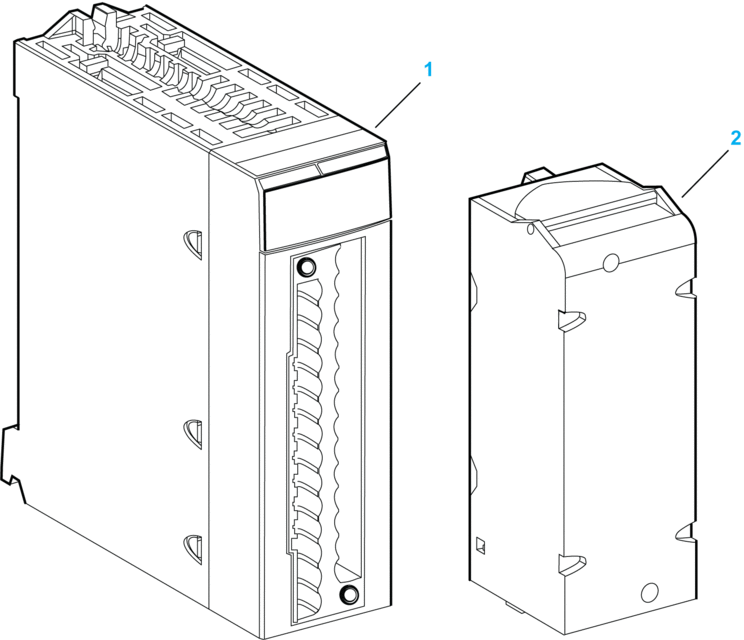
1 Module with its LED display
2 28-pin removable terminal block
LED display:
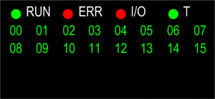
The following table describes the LED display activity meaning for diagnostic purpose:
LED |
Status |
Description |
|---|---|---|
ERR |
ON |
The module has an internal detected error. |
Flashing (with RUN LED OFF) |
The module is not configured. |
|
The module is configuring its channels. |
||
Flashing (with RUN LED ON) |
The module has lost the communication with the PLC CPU. |
|
I/O |
ON |
Field power supply failure detected. |
T |
ON |
The module clock is synchronized with the external time source connected. |
Flashing (with RUN LED Flashing) |
Firmware is being downloaded. |
|
Quick flashing |
Module clock synchronization error detected: External time clock is temporarily unstable but the internal time quality is acceptable. |
|
OFF |
No external time source input. |
BMx CRA 312 10 Module View
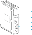
1 LED display
2 rotary switches
3 SERVICE port (ETH 1)
4 DEVICE NETWORK port (ETH 2)
5 DEVICE NETWORK port (ETH 3)
LED display:

The following table describes the LED display activity meaning for diagnostic purpose:
Module State(1) |
Description |
Run |
IO |
MS (Module Status) |
NS (Network Status) |
||||
|---|---|---|---|---|---|---|---|---|---|
Green |
Red |
Green |
Red |
Green |
Red |
||||
power-up sequence |
Order of LEDs blinking |
1 |
2 |
3 |
4 |
5 |
6 |
||
not configured |
IP address not valid |
- |
- |
flashing |
off |
off |
off |
||
valid IP address, but invalid configuration |
off |
off |
flashing |
off |
flashing |
off |
|||
configured |
no external error detected |
flashing |
off |
- |
- |
flashing |
off |
||
external error detected |
flashing |
on |
- |
- |
flashing |
off |
|||
I/O data communication established |
STOP |
flashing |
(NOTE 1) |
on |
off |
on |
off |
||
RUN |
on |
(NOTE 2) |
on |
off |
on |
off |
|||
detected error states |
recoverable |
- |
- |
off |
flashing |
- |
- |
||
nonrecoverable |
flashing |
on |
off |
on |
- |
- |
|||
duplicate IP address |
- |
- |
- |
- |
off |
on |
|||
during OS firmware update |
flashing |
off |
off |
on |
off |
on |
|||
NOTE 1 (STOP state):
NOTE 2 (RUN state):
|
|||||||||


