Time Stamping Module Internal Buffer Full
A time stamping module internal event buffer should not be full in normal case, but it can become full in case of disconnection between the module and the SCADA system for example.
A buffer full is diagnosed from the PLC via BUFF_FULL parameters in , or , or system word, or TS_BUF_FILLED_PCTAGE parameter. On a BME P58 •••• CPU, TS_BUF_FILLED_PCTAGE parameter is located
on %SW74.8...%SW74.15.
Time stamping modules stop the recording on buffer full in a system time stamping solution. The process values continue to change but as the source module buffer is full, they cannot be stored.
SOE Sequence on Buffer Full
Sequence followed after detection of a buffer full:
Stop the detection and storage of events. The last input (and output) values are frozen (historical values).
Signalization of the beginning of an uncertain sequence of events (see following table, sequence number 1).
Wait for the time stamping module buffer to have a percentage of free space again (time elapsed between sequence number 1 and sequence number 2 in the following table). Space is freed in the buffer when the SCADA reads it.
Time stamping module buffer is read by the SCADA server and has free space again.
Detection of input (and output) value changes. Changes are detected by comparing the current I/O value with the historical value stored when the buffer became full.
Storage of all the I/O detected changes with
TimeQuality= Invalid (see following table, sequences number 2 to 4).Signalization of the end of an uncertain sequence of events (see following table, sequence number 5).
Start the detection and storage of new events.
Normal time stamping (see following table, sequences 6, 7 and next).
The following table presents the SOE sequence on buffer full provided by a BMX CRA 312 10 time stamping module with 3 time stamped inputs and 1 time stamped output:
Sequence Number |
Event |
Event Value |
TimeStamp |
|
|---|---|---|---|---|
1 |
(0 -> 1) |
1 |
Internal CRA time |
Time Resolution = 1 ms |
2 |
CRA INPUT 1 (1 -> 0) |
0 |
Internal CRA time |
Invalid |
3 |
CRA INPUT 3 (0 -> 1) |
1 |
Internal CRA time |
Invalid |
4 |
CRA OUTPUT 4 (1 -> 0) |
0 |
Internal CRA time |
Invalid |
5 |
(1 -> 0) |
0 |
Internal CRA time |
Time Resolution = 1 ms |
6 |
CRA INPUT 1 (0 -> 1) |
1 |
Internal CRA time |
Time Resolution = 1 ms |
7 |
CRA INPUT 3 (1 -> 0) |
0 |
Internal CRA time |
Time Resolution = 1 ms |
Example of SCADA View on Buffer Full Sequence
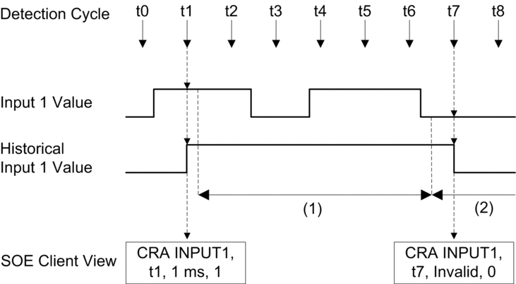
The following picture shows the Input 1 of BMX CRA 312 10 module changes read by the SCADA server and the associated timing when the BMX CRA 312 10 buffer becomes full, and then free again:

(1) Buffer full, detection of events stopped and historical frozen.
(2) Detection of events starts again.
Sequence followed on buffer full event detection description:
| t0 | Buffer is not full, normal time stamping mode. |
| t1 | Buffer is not full, normal time stamping mode. BMX CRA 312 10 Input 1 value change detected, historical takes the current value. |
| t2 | Buffer full detected, no time stamping on this module, last Input 1 value is frozen (historical). |
| t3 ... t6 | Buffer full, no time stamping on this module. |
| t7 | Buffer not full detected (enough percentage of the buffer is free). BMX CRA 312
10 Input 1 value compared with the historical value: 1
to 0 change detected, storage of the event CRA Input 1 (1 to
0) in the buffer with |
| t8 | Buffer is not full, normal time stamping mode, Time Resolution = 1 ms. |


