The insertion of BMXNRP020 fiber converters in a Quantum EIO network enables conversion from copper cable to fiber optic cable and the other way around in different network topologies.
NOTE: A fiber converter does not count as a device in your main ring capacity calculation.
Connecting to X80 and Quantum EIO Drops
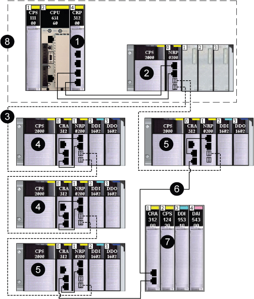
Use BMXNRP020 fiber converters to connect one or more Quantum EIO drops to a fiber main I/O ring with daisy chain loop management:
- - -
fiber cable
copper cable
1
140CRP31200 remote I/O head module on the local rack connected via copper cable to a transceiver port of a BMXNRP020 fiber converter
2
BMXNRP020 fiber converter connected via copper cable to the 140CRP31200 head module and connected via fiber cable to the BMXNRP020 fiber converter on a subsequent X80 drop
3
fiber portion of the main ring
4
X80 drops connected to the main ring via fiber cable
5
X80 drop connected to the main ring via fiber and copper cable the BMXNRP020 fiber converter connects the drop to the main ring via fiber, and the BMXCRA31200 adapter module connects the Quantum EIO drop to the main ring via copper cable
6
copper portion of the main ring
7
Quantum EIO drop connected to the main ring via copper cable (No BMXNRP020 fiber converter is required.)
8
Local area with local main rack and local extended rack
Fiber Connection Between a Quantum Main Rack and Quantum EIO Drops
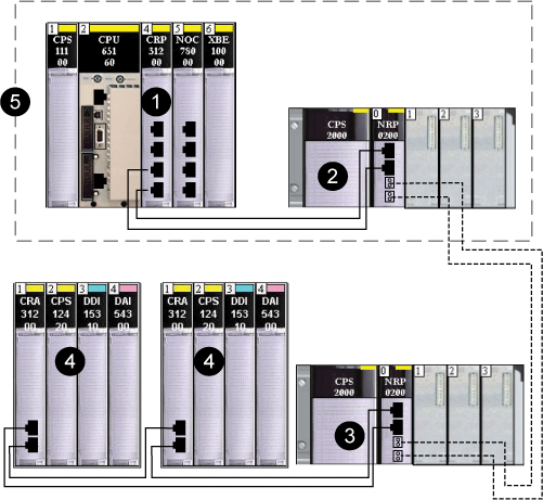
Use BMXNRP020 fiber converters to connect one or more Quantum EIO drops with daisy chain loop management:
- - -
fiber cable
copper cable
1
140CRP31200 remote I/O head module on the local rack connected via copper cable to a transceiver port of a BMXNRP020 fiber converter
2
BMXNRP020 fiber converter connected via copper cable to the 140CRP31200 head module and connected via fiber cable to the BMXNRP020 fiber converter on a subsequent X80 drop
3
BMXNRP020 fiber converter connected via copper cable to the 140CRA31200 drop module(s) and connected via fiber cable to the BMXNRP020 fiber converter
4
Quantum EIO drop connected to the main ring via copper cable
5
Local area with local main rack and local extended rack
Creating a Long-Haul Hot Standy Link
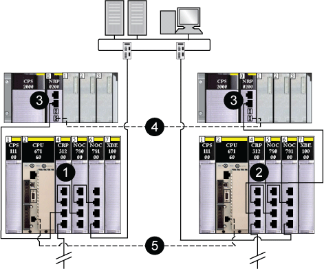
The following graphic shows the installation of BMXNRP020 fiber converters to extend the distance between the 2 PLCs beyond 328 ft (100 m):
1
140CRP31200 remote I/O head module on the primary Hot Standby PLC connected to a copper port of a BMXNRP020 fiber converter
2
140CRP31200 remote I/O head module on the secondary Hot Standby PLC connected to a copper port of a BMXNRP020 fiber converter
3
BMXNRP020 fiber converters on local extended racks connected via copper cable to 140CRP31200 head modules on the local racks
4
fiber cable connected to the fiber ports of the BMXNRP020 fiber converters to extend the distance between the Hot Standby PLCs beyond 328 ft (100 m)
5
fiber cable used for the CPU-sync link
NOTE: Connect the fiber optic cable between the 2 fiber converters (3) straight through. No EIO drops are allowed on this link.
High-Capacity Daisy Chain Loop Topology
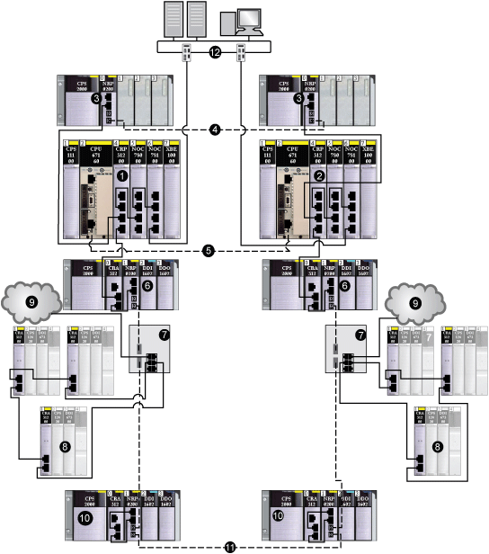
Use BMXNRP020 fiber converters to extend the distance between the main local rack and sub-rings or distributed I/O devices beyond 328 ft (100 m).
- - -
fiber cable
copper cable
1
140CRP31200 remote I/O head module on the primary Hot Standby PLC connected to a copper port of a BMXNRP020 fiber converter
2
140CRP31200 remote I/O head module on the secondary Hot Standby PLC connected to a copper port of a BMXNRP020 fiber converter
3
BMXNRP020 fiber converters on extended local racks connected via copper cable to 140CRP31200 head modules on the local racks
4
fiber cable connected to the fiber ports of the BMXNRP020 fiber converters to extend the distance between the Hot Standby PLCs beyond 328 ft (100 m)
5
fiber cable used for the CPU-sync link
6
BMXNRP020 fiber converters on X80 Ethernet remote I/O drops connected to DRSs via fiber cable
7
DRSs (with a C3 predefined configuration file) connecting Quantum Ethernet remote I/O sub-rings and distributed I/O clouds to the main ring via copper cable
8
Quantum Ethernet remote I/O sub-rings
9
distributed I/O clouds
10
BMXNRP020 fiber converters on X80 Ethernet remote I/O drops connected to DRSs via fiber cable and connected to each other
11
fiber cable connecting two X80 Ethernet remote I/O drops to extend the distance beyond 100 m
12
control network
NOTE: You can install BMXNRP020 fiber converters on the main ring and sub-rings for copper-to-fiber conversion and vice-versa. However, you cannot use these modules to connect sub-rings to the main.


