|
Software Configuration
|
|
|
Original instructions
|
|
Step
|
Action
|
|---|---|
|
1
|
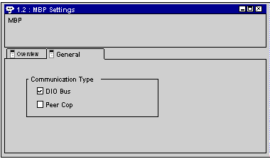
Select the Modbus Plus connection that you want to configure as a DIO Bus from the Project Browser or in the hardware configuration window.
The following configuration window is opened:
 |
|
2
|
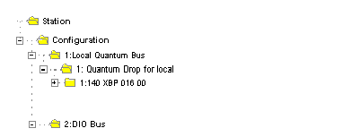
Activate the DIO Bus check box in the configuration window and confirm your entry.
A DIO Bus is placed in the Project Browser:
 |
|
3
|
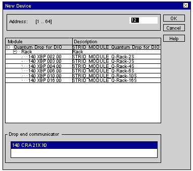
Open the DIO Bus and select add module rack and select New Device.
The module rack selection list is opened:
 |
|
4
|
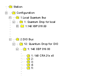
Select the desired module rack and enter the Modbus Plus address in the address field. Confirm with OK.
A DIO Drop is placed in the Project Browser. The number set, 12 in our example, states the Modbus Plus address of the Drop. The Modbus Plus Coupler 140 CRA 21X X0 is automatically entered in slot 1:
 |
|
5
|
To continue configuring the RIO Drop you can carry on as with configuring a local I/O.
|