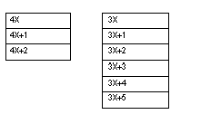
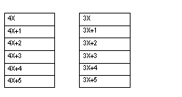
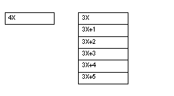
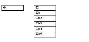
The 140 EHC 202 00 high speed counter requires six contiguous output (4X) and six contiguous input (3X) registers in the I/O map.
The 4X registers perform the same configuration tasks as in the Parameter Configuration. Also, the preset and the enable inputs connected to the field wiring terminal block perform the same functions as those software command control bits. When both methods are used to:
-
Preset a counter – the last preset executed has precedence.
-
Enable/disable a counter – it will only be enabled when both the hardware enable input and software enable control bit are in the enable state.
For simple applications, the parameter configuation rather than the I/O mapped registers can be used to configure the module. Parameter configuration is only possible while the PLC is stopped. The selected parameters take effect when the PLC is set to run. For applications that require that module parameters be changed while the system is running, user logic can modify the I/O map-assigned registers to override the previously selected parameters.
When using either parameter configuration or I/O map registers, the maximum values specified in the Load Values Command section are the largest values that can be used by the module.
The I/O Mapped registers discussed in this section are 4X output registers that:
-
Preset and enable/disable input counters.
-
Load setpoint and maximum values to define output turn on points.
-
Set mode of operation, count, or rate sample.
-
Enable output switches and configures their mode of operation.
3X input registers that:
-
Hold count or rate sample data.
-
Display field power status.
-
Echo 4X command data after the command is executed by the module.
There are four command that can be performed. Each uses one or more of both types of registers assigned to the module. In addition to the command definition byte, the first 4X register for all commands contain control bits to preset and enable/disable counters of either channel.
Command 1 uses three 4X registers and six 3X registers (see below).
The following figure shows the 4X and 3X registers for command 1.
This command does the following:
-
Sets up the module for pulse or quadrature input.
-
Sets up the module for count or rate-sample mode. Counters cannot be separately configured.
-
Defines counter register length – 16 or 32 bit.
-
Enables output assertion including module communication loss state. Output assertion is available if configured for 2, 16 bit, or 1, 32 bit counter. No output assertion is available if 2, 32 bit counters are defined, or in rate-sample mode.
-
Defines output assertion point.
There are four formats for this command. It uses up to six 4X registers and six 3X registers.
The following figure shows the format for registers 4X and 3X for command 2.
Values loaded may be the following.
-
Maximum count and setpoint (i.e., output turn on times).
-
Output assertion ON time duration (one input only).
-
Rate sample time interval.
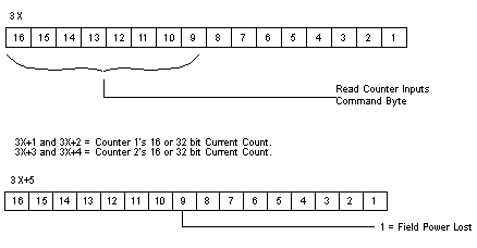
Command 3 - READ INPUT COUNTER
Command 3 uses one 4X register and six 3X registers (see below).
The following figure shows the 4X and 3X registers for command 3.
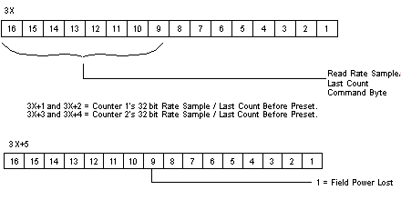
Command 4 READS RATE SAMPLE or LAST INPUT COUNT BEFORE PRESET
Command 4 uses one 4X register and six 3X registers (see below).
The following figure shows the 4X and 3X registers for command 4.
NOTE: 4X register formats for the commands are described first. The 3X register contents after issuing Command 1 or 2 are listed after the 4X register description for Command 2, since the responses are the same for both. The 3X responses for Commands 3 and 4 immediately follow those commands.
NOTE: When Command 0 (4X = 00XX) or any other undefined commands are asserted in the 4X register, the 3X registers will contain the count inputs if in count mode (same as Command 3) and the rate sample values when in rate-sample mode (same as Command 4).
The following details the command words and responses.
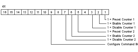
Command 1 - CONFIGURE, Output Register Format (4X = 01XX hex)
The following figure shows the 4x output register for command 1.
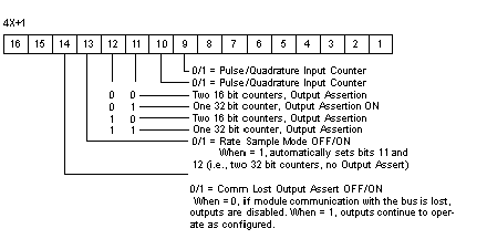
The following figure shows the 4x + 1 output register for command 1 (4X+1).
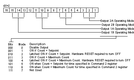
The following figure shows the 4x +2 output register for command 1.
NOTE: The Output ON time specified in the Command 2 registers may be used by only one of the four outputs. When more than one output is set to mode 5 or 6, the module firmware will operate the first one encountered, and disable the other outputs set to modes 5 or 6.
Command 2. LOAD VALUES, Output Register Format (4X = 02XX hex)
The LOAD VALUES 4X register format depends on the Counter/Rate Sample mode selected in Command 1, Register 4X+1, bits 11 and 12.
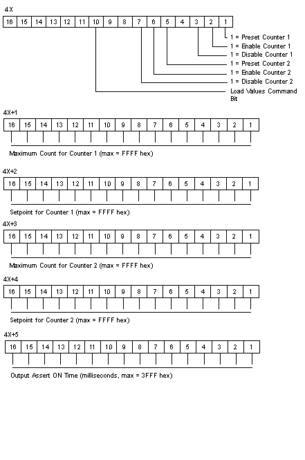
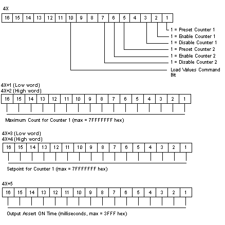
If configured for two, 16 bit Counters - Output Assert ON, the following information is displayed.
The following figures show the counters for registers 4X through 4X+5 modules.
NOTE: Zero set into any 4X register means no change.
If configured for one, 32 bit Counter - Output Assert ON, the following information is displayed.
The following figure shows the counters for registers 4X through 4X+5, with low and high word.
NOTE: Zero set into any 4X register pair for 32 bit values or any 4X register means no change.
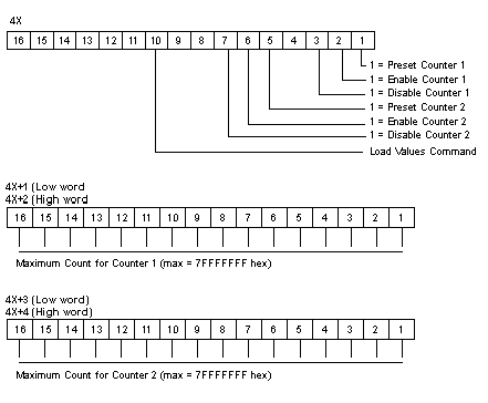
If configured for 2, 32 bit Counters - NO Output Assert, the following information is displayed.
The following figures show the 4X through 4X+4 counters, with low and high word.
NOTE: Zero set into any 4X register pair for 32 bit values or any 4X register means no change.
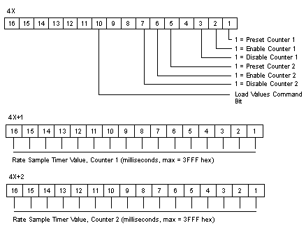
If configured for Rate Sample Mode, the following information is displayed.
The following figure shows the 4X through 4X+2 counters.
NOTE: Zero set into any 4X register or any 4X register pair for 32 bit values means no change.
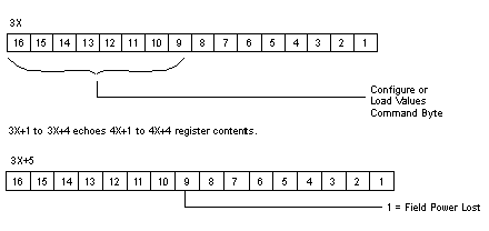
Command 1 and Command 2 Response Formats
The following figures show the 3X through 3X+5 response formats.
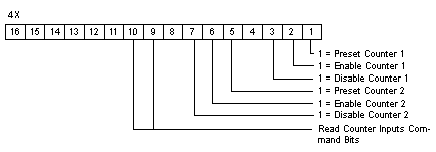
Command 3, READ INPUT COUNTER, Output Register Format (4X = 03XX hex)
The following figure shows the 4X register for command 3.
Command 3 Response Format
The following figure shows the command 3 response format.
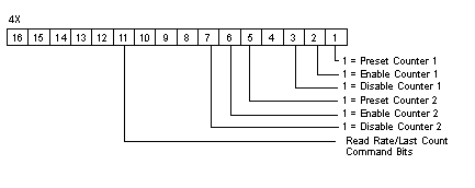
Command 4, READ RATE SAMPLE or READ LAST COUNT VALUE BEFORE MOST RECENT PRESET, Output Register Format (4X = 04XX hex)
The following figure shows the 4x counters for command 4.
Command 4 Response Format
The following figures show the counters for 3X through 3X+5 for command 4.
The most significant bit in the I/O Map status byte is used for the 140 EHC 202 00 High Speed Counter Module.
The following figure shows the map status byte register.
Field connections for this example are illustrated in the EHC 202 wiring diagrams 1-4. The maximum allowable Vref value is 30 VDC. Input pulse on-off threshold levels for the 5 ... 24 VDC Vref range are listed in the module specification table. The minimum differential input is 1.8 V.
The following user logic:
-
Configures the module to count up from zero.
-
Turns an output on for one count at a setpoint value of 50.
-
Continues counting to 100.
-
Rolls over to zero and turn on a second output for one count.
-
Repeats the operation.
The following table shows the I/O Map register assignments.
|
Input Ref
|
Output Ref
|
|
300001-300006
|
400001-400006
|
In this example, block moves are used to load the operating parameters into the module. This requires pre-defined tables be established. Register values are in HEX format.
Module Configuration Table
The following table shows the module configurations.
|
400101 0140
|
CONFIGURE command, Disable Counter 2
|
|
400102 0000
|
Pulse input, two 16 bit counters, output assert on Rate Sample OFF, disable outputs at bus communication loss
|
|
400103 3100
|
Output 1A on at setpoint, Output 1B on at maximum count +1 Output 2A and 2B are disabled
|
|
400104 0000
|
Not used by this command
|
|
400105 0000
|
|
400106 0000
|
The following table shows the load values.
|
400201 0243
|
LOAD VALUES command, disable Counter 2, preset and enable Counter 1
|
|
400202 0064
|
Counter 1 maximum count, count after which Output 1B turns on
|
|
400203 0032
|
Counter 1 setpoint, count when Output 1A turns on
|
|
400204 0000
|
Counter 2 maximum count (not used in this example)
|
|
400205 0000
|
Counter 2 setpoint (not used in this example)
|
|
400206 0000
|
Output assert time (Not used in this example, one output only, fused
|
Zeros in the 4X registers also mean no change. Setpoint, maximum count and assert time can only be set to zero using the parameter configuration. When the registers in this example are echoed, zeros will appear but the actual content in the module will be unchanged from previous values. In this example, Counter 2 is disabled and its outputs and timed assert have not been selected. Registers 400204 - 6 have no meaning.
After the module executes the Configure and Load Value’s commands, they are echoed in the I/O mapped 3X registers except for the command register’s low 8 bits. Command execution time by the module is 1 ms. Actual time between the 4X register block move and the echo response display in the 3X registers is dependent on User Logic and hardware configuration. An echo of the Configuration command registers would appear as follows:
The following table shows the echo response for the configuration command.
|
Register
|
Value
|
|
300001
|
0100
|
|
300002
|
0000
|
|
300003
|
3100
|
|
300004
|
0000
|
|
300005
|
0000
|
|
300006
|
0000
|
The following table shows the read input registers.
|
40301
|
0300
|
READ INPUT COUNTER command
|
|
40302
|
0000
|
Not used by this command
|
|
40303
|
0000
|
|
40304
|
0000
|
|
40305
|
0000
|
|
40306
|
0000
|
When this command is issued, the content of the input pulse counter is retrieved. The 3X register content would appear as follows:
The following table shows the content of the registers.
|
Register
|
Value
|
Description
|
|
300001
|
0300
|
Command echo
|
|
300002
|
XXXX
|
Current input count
|
|
300003
|
0000
|
Zeros as the count will not exceed 100. For counts above 65,536, this register is a multiplier. As an example: 30002 has a value of 324 and 30003 a value of 3.The total count is (65,536 x 3) + 324 = 196,932
|
|
300004
|
0000
|
Counter 2 is disabled
|
|
300005
|
0000
|
Counter 2 is disabled
|
|
300006
|
0X00
|
X is the field power indicator
|
If register 400103 in the Module Configuration Table has been set to 4200, Output 1A would have been latched on at setpoint and Output 1B latched on at maximum count. Wiring Diagrams 2 and 4 show how the encoder Z outputs could be used to reset the latched outputs. The minimum pulse width to reset outputs is 1 ms.
The COUNT DOWN example uses the same wiring as in the count up example, except the Input 1B+ level is changed to common (connected to Vref-) for Pulse Inputs illustrated in Wiring Diagrams 1 and 2. For Quadrature Inputs, no wiring change is required as the count direction is decoded internally by sensing the phase shift change between inputs A and B.
The User Logic is the same as for the count example. The actual operation of the module is different in that the output associated with maximum count turns on after zero count has been reached.
The example configures the module to decrement the input count from the maximum value, turn on an output at a setpoint value of 50, and turn on a second output after the input counter had reached zero and rolled over to the maximum count; the operation is then repeated. The initial loading of the maximum count will not cause its associated output to turn on.
RATE SAMPLE Example for Either Pulse or Quadrature Input
Field connections for this example are illustrated in the Wiring Diagrams1-4. The connections on terminals 15 and 16 are optional, depending on the use requirements of the outputs. Terminals 39 and 40 always require the 24 VDC supply connections. The maximum allowable Vref value is 30 VDC. Input pulse on-off threshold levels for the 5 ... 24 VDC Vref range are listed in the module specification table. The minimum differential input is 1.8 V.
As with count examples, tables are set up and transferred to the module using block moves. The User Logic for Rate Sample is the same as that used for Pulse Input Count Up/Down.
Module Configuration Table
The following table shows the module configurations.
|
400101 0140
|
CONFIGURE command, Disable Counter 2
|
|
400102 1000
|
Pulse input, Rate Sample ON, disable outputs at bus communication loss (Note: Bits 11 and 12 were not required.)
|
|
400103 0000
|
Not used by this command
|
|
400104 0000
|
|
400105 0000
|
|
400106 0000
|
The following table shows the load values.
|
400201 0243
|
LOAD VALUES command, disable Counter 2, preset and enable Counter 1
|
|
400202 XXXX
|
Counter 1 Rate Sample Time in milliseconds
|
|
400203 0000
|
Counter 2 Rate Sample Time in milliseconds (Not used in this example)
|
|
400204 0000
|
Not used by this command
|
|
400205 0000
|
|
400206 0000
|
NOTE: Command echoes are the same as described in the Pulse Input Count Up/Down examples.
The following table shows a read rate sample.
|
400301 0400
|
READ INPUT COUNTER command
|
|
400302 0000
|
Not used by this command
|
|
400303 0000
|
|
400304 0000
|
|
400305 0000
|
|
400306 0000
|
When this command is issued, the input pulse counter content is retrieved. The 3X register content is the count over the time period selected in the Load Values registers 4X + 1 and 4X + 2. The 3X response to the Read-Rate Sample command in register 40301 is as follows.
The following table shows the responses to the read rate sample command.
|
Register
|
Value
|
Description
|
|
300001
|
0400
|
Command echo
|
|
300002
|
XXXX
|
Counter 1 Input rate low word
|
|
300003
|
XXXX
|
Counter 1 Input rate high word: this register is a multiplier. As an example: 30002 has a value of 324 and 30003 a value of 3.The total count is (65,536 x 3) + 324 = 196,932
|
|
300004
|
0000
|
Counter 2 is disabled
|
|
300005
|
0000
|
Counter 2 is disabled
|
|
300006
|
0X00
|
X is the field power indicator
|
NOTE: If a version 02.00 or higher module replaces a module which has a version number less than 02.00 in a Rate Sample mode application, extra software configuration may be required.
Rate Sample mode is set using Command 1, CONFIGURE (01XX), 4X+1 register, bit 13 = 1 (see the description of Command 1 in this section).
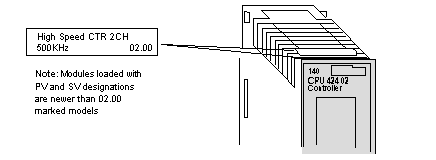
To verify the version of the module, reference the indicated label found on the top front of the module.
The following figure shows the module’s label.
In modules prior to V02.00, when Rate Sample mode was selected, input was always handled as if it were generated by a pulse encoder. For example, 60 count per revolution encoders, either pulse or quadrature types, would give a rate of 60 for a one-second revolution when the interval was set for one second.
NOTE: Beginning with V2.00 modules, if a quadrature type encoder is used to provide count input and Pulse/Quadrature Input Counter 1 and 2, bits 9 or 10, are set to 1, the module will detect all edges.
The result is four times the rate sample value as would be accumulated with an equivalent pulse encoder input. In the example in the above paragraph, the rate sample would be equal to 240.
Encoder type selection is set using Command 1, CONFIGURE (01XX), 4X+1 register, bits 9 or 10 (see the description of Command 1 in this section).
If the Encoder Type select bits are set to 0, either type of encoder will produce the Rate Sample, as did versions of the module that were lower than V02.00.
