|
Wiring
|
|
|
Original instructions
|
|
Parameter
|
Description/Usage
|
|
INPUT A
|
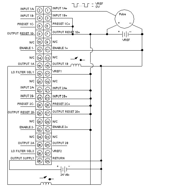
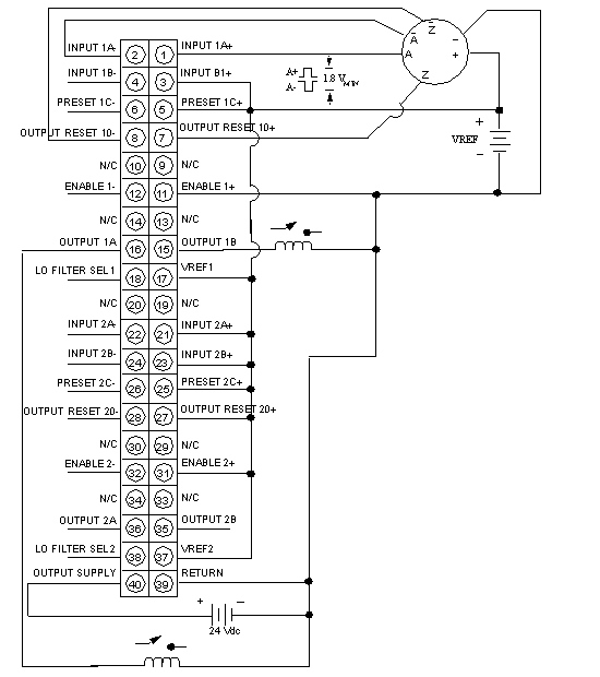
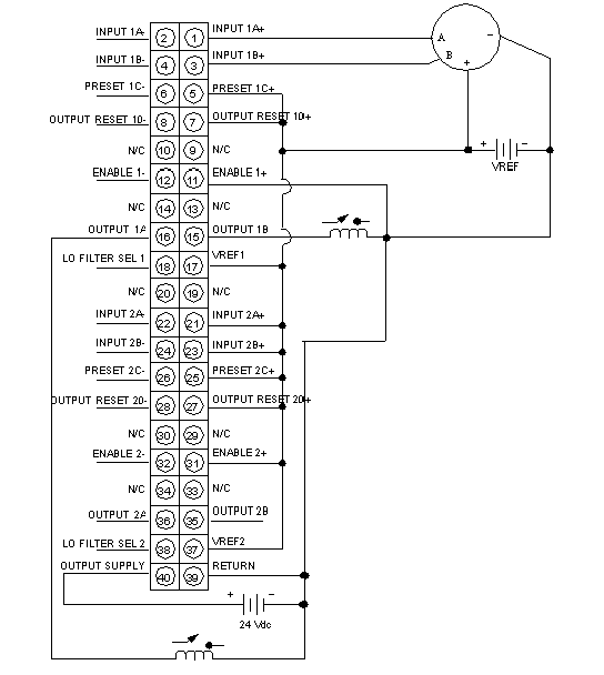
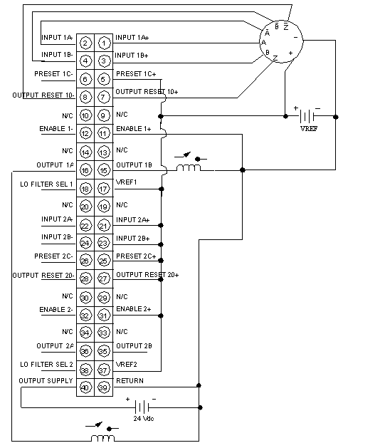
Single ended or differential count input or Phase A for quadrature mode.
|
|
Single ended (active low only) uses Input 1A+ and/or Input 2A+.
|
|
|
Input 1A- and/or Input 2A- are not connected. Differential input encoders use both plus (+) and minus (-) inputs.
|
|
|
INPUT B
|
Direction level for non-quadrature devices or Phase B for quadrature mode.
|
|
Direction inputs for non-quadrature input devices are: Count Up = High Voltage Level; Count Down = Low Voltage Level
|
|
|
For single ended Input devices, only Input 1B+ and/or Input 2B+ are used. Input 1B- and 2B- are not connected. Differential input encoders use both plus (+) and minus (-) inputs.
|
|
|
PRESET C
|
Presets count register(s). Low level causes preset.
|
|
For single ended Preset inputs, only Preset 1C+ and/or Preset 2B+ are used. Preset 1C- and 2C- are not connected. Differential input encoders use both plus (+) and minus (-) inputs.
|
|
|
OUTPUT RESET 0
|
Low level resets Outputs 1A, 1B, 2A, and 2B to OFF if latched.
|
|
For single ended Reset inputs, only Reset 10+ and/or Reset 20+ are used. Reset 10- and 20- are not connected. Differential input encoders use both plus (+) and minus (-) inputs.
|
|
|
ENABLE
|
Low level enables counting.
|
|
For single ended Enable inputs, only Enable 1+ and/or Enable 2+ are used. Enable 1- and 2- are not connected. Differential input encoders use both plus (+) and minus (-) inputs.
|
|
|
VREF
|
Field input device power source connection. Also, connect any unused (+) inputs to the group VREF terminal or the one in use (30 Vdc max).
|
|
Group A = Terminal 17
|
|
|
Group B = Terminal 37
|
|
|
Group A and Group B VREF supplies can be different voltage levels.
|
|
|
LO FILTER SEL
|
Enables the internal 200 Hz filter when connected to Return Terminal 39.
|
|
OUTPUT
|
Internal FET switches connect the output supply wired to Terminal 40 to the Output 1A, 1B, 2A, 2B terminals at output assert times.
|
|
POWER SUPPLY
|
External 24 Vdc power supply (+) connection. Required for the module interface and for Outputs 1A, 1B, 2A, and 2B.
|
|
RETURN
|
External 24 Vdc power supply (-) connection. Required for the module interface and for Outputs 1A, 1B, 2A, and 2B.
|


