The 140 CRA 212 20 is a dual channel Distributed I/O Interface, connected via a twisted pair Modbus Plus cable network. This DIO Drop Module provides the I/O with power from a 24 VDC source.
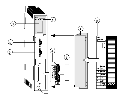
The following figure shows the parts of the distributed I/O (DIO) module.
1
LED Area
2
Modbus Plus Connector (Channel A)
3
Modbus Plus Connector (Channel B)
4
Field Wiring Connector
5
Field Wiring Connector Cover
6
Model Number, Module Description, Color Code
7
Removable Door
8
Customer Identification Label (Fold label and place it inside door)
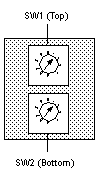
Two rotary switches (refer to the illustration and table below) are located on the rear panel of the CPU. They are used for setting Modbus Plus node addresses for the unit.
SW1 (the top switch) sets the upper digit (tens) of the address; SW2 (the bottom switch) sets the lower digit (ones) of the address. The illustration below shows the correct setting for an example address of 11.
Rear Panel Switches Figure
The following figure shows the SW1 top switch and the SW2 bottom switch.
Rear Panel Switches Table
The following table shows the node addresses of the SW1 and SW2 switches.
|
Node Address
|
SW1
|
SW2
|
|
1 ... 9
|
0
|
1 ... 9
|
|
10 ... 19
|
1
|
0 ... 9
|
|
20 ... 29
|
2
|
0 ... 9
|
|
30 ... 39
|
3
|
0 ... 9
|
|
40 ... 49
|
4
|
0 ... 9
|
|
50 ... 59
|
5
|
0 ... 9
|
|
60 ... 64
|
6
|
0 ... 4
|
NOTE: Only addresses from 1 to 64 are valid.
If "0" or an address greater than 64 is selected, the "Modbus+" LED will be ON, steady, to indicate the selection of an invalid address.

