Fiber Optic Cable Connections
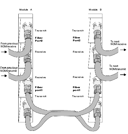
The NOM 252 00 module is connected in the Quantum system by a fiber optic cable (see below). The cable has two strands. Each module transmits a uni-directional signal. For this reason, each strand must be connected to the transmit port on one module and the receive port on the other.
One strand of the fiber optic cable is marked at 10-inch (25 cm) intervals with the manufacturer’s name and the cable specifications. This is the only way to distinguish the two strands.
Fiber Optic Cable Connections Figure
The following figure shows the fiber optic cable connections.
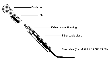
Connecting the Fiber Optic Cable
The following steps show how to connect the fiber optic cable.
|
Step
|
Action
|
|
1
|
Remove the protective plastic coverings from the cable ports and the tips of the cable. Snap one of the fiber cable clasps (shipped with the module) over the cable so that the wider end of the tool is closest to the cable end.
|
|
2
|
Turn the connection ring so that one of the arrows on the side of the ring lines up with the ridge inside.
|
|
3
|
a. Slide the tool up to the connection ring.
b. Gripping the cable with the plastic cable clasp, slide the cable end onto the lower cable port. The arrow and the ridge on the connection ring should line up with the slot on the left of the cable port.
c. Use the clasp to push the cable over the tab on top of the port.
d. Turn the cable to the right, so that the tab locks securely
e. Remove the clasp.
f. Repeat this process with the remaining strand of cable.
|
Fiber Optic Configurations
Here are four typical configurations that show the wide range of the network architecture:
Point-to-Point Configuration
This type of configuration (see below) allows communication over the distance of up to 3 km through harsh industrial environments.
Point-to-Point Configuration Example Figure
The following figure shows the point-to-point configuration.
This type of configuration is used when it is required to connect a number of fiber nodes and can be used to increase the distance of a standard Modbus Plus network by changing to a fiber medium. This kind of network allows the connection of up to 32 Quantum NOM 252 nodes over the distance of 5 km.
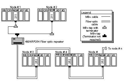
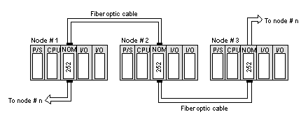
The following illustrations show the NOM 252 00 module in a mixed fiber optic/twisted pairs bus configuration network and a straight fiber optic bus configuration network.
NOTE: The loss of a single node in this configuration disables the rest of the network.
Bus Configuration Example 1
The following figure shows the mixed fiber optic/copper network.
Bus Configuration Example 2
The following figure shows the straight fiber optic network.
NOTE: The distance between nodes on fiber is limited by the maximum allowable power loss from end-to-end (3 km over 62.5 mm fiber). Power loss includes the fiber optic cable attenuation, connector losses at the Fiber Optic Receiver and Transmitter ports, and the system margin of 3 dB.
In this configuration, the end NOM 252 00 in this configuration will have the FRNGoff LED active. It also displays the Cable B Framing error in the MBPSTAT (in ladder logic).
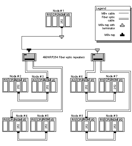
Using tree configurations allows for greater flexibility in the layout of Modbus Plus and NOM 252 00 networks. The following illustrations are samples tree configurations. Additional repeaters may be connected in order to extend communication between electrical links.
Tree Configuration Example
The following figure shows the tree configuration.
Self-healing Ring Configuration
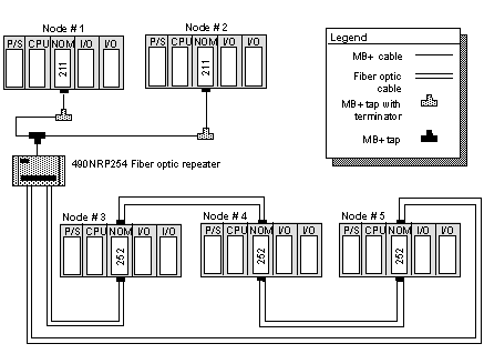
This configuration can be achieved by connecting the unused fiber optic ports of the first and last NOM 252 00 directly or through the fiber optic repeater, if a mixed fiber optic/twisted pairs network is used. This type of connection has all the advantages of the previously described configurations, along with built-in redundancy. A broken connection between any two Quantum modules in the ring will automatically reconfigure the network to the bus configuration, and maintain communication.
Self-healing Ring Configuration Example
The following figure shows a self-healing ring configuration example.
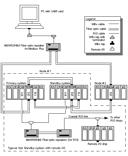
Hot Standby Systems Figure
The following figure shows the self-healing ring configuration for hot standby systems.
The information about the condition of the network is presented in the form of Network Status. This information indicates the loss of connection (the first break in the self-healing ring) and is similar to the way the existing 140 NOM 212 00 reports the loss of the redundant cable.
The break in the fiber cable will be detected by the module not receiving the signal from the cable break side. The incident will be reported by MBPSTAT as a Cable B Framing error. This condition also activates the FRNGoff LED on the module front.
Recommended Materials for Fiber Optic Links
Modicon does not manufacture fiber optic products such as cables, connectors, or special tools. However, we have experience with third party suppliers of materials, and are able to provide guidelines on product compatibility.
The following table shows the connector types
|
Connector type
|
Part number
|
Operating temperature
|
|
ST bayonet (epoxy)
|
3M 6105
|
-40 ... +80 °C
|
|
ST bayonet (hot melt)
|
3M 6100
|
-40 ... +60 °C
|
|
ST bayonet (epoxy)
|
AMP 501380-5 series
|
-30 ... +70 °C
|
|
ST bayonet (epoxy)
|
AMP 503415-1 series
|
-20 ... +75 °C
|
|
Light crimp ST-style
|
AMP 503453-1 series
|
-20 ... + 60 °C
|
|
Mechanical line splice (one size fits all)
|
3M 2529 Fiberlok1 II
|
-40 ... +80 °C
|
NOTE: All connectors must have a short boot for strain relief.
The following table shows the termination kits.
|
Kit type
|
Part number
|
Description
|
|
Bayonet ST (eoxy)
|
AMP 503746-1
|
For all epoxy type ST style
|
|
Light crimp XTC
|
AMP 50330-2
|
For all light crimp
|
|
Mechanical line splice
|
3M 2530
|
Fiber splice prep kit, complete with cleaving tool
|
|
3M hot melt
|
3M 05-00185
3M 05-00187
|
110 V termination kit
220 V termination kit
|
The following table shows other tools that may be needed for fiber optic links.
|
Product
|
Part number
|
Description/use
|
|
3M (Photodyne) optical source driver
|
9XT
|
Hand-held optical source driver (requires a light source)
|
|
3M (Photodyne) optical light source
|
1700-0850-T
|
850 nm Light Source, ST Connectors for 9XT
|
|
3M (Photodyne) power meter
|
17XTA-2041
|
Hand-held fiber optic power meter
|
|
3M optical light source, 660 nm, visible
|
7XE-0660-J
|
Use with 9XT to troubleshoot raw fiber, requires FC/ST patch cord
|
|
3M FC/ST patch cord
|
BANAV-FS-0001
|
Connects FC connector on 7XE to ST
|
|
3M bare fiber adapter, ST-compatible
|
8194
|
Allows the use of above source and meter to test raw fiber (two required)
|
It is recommended that you use 62.5/125 mm cable (such as AMP 503016-1, AMP 502986-1, or equivalent) with a maximum attenuation of 3.5 dB/km in most of the configurations.
NOTE: Modicon recommends using the 52-0370-000 cable.
NOTE: All cables must have a maximum cable diameter of not more than 3 mm at the terminal side.
The following information discusses connecting the NOM 252 00 on fiber cable, adding a new mode to the network, and repairing the break in the cable.
NOTE: When a new network is assembled, it is recommended that you connect all cables before powering up the system. Connect fiber optic cables as described previously in this section.
Adding a New Node to the Network
If a new node is added to an existing network in order to extend the network (at the end of any configuration), then a new node may be connected first by fiber cable and then hot-swapped to the backplane to avoid errors to the existing network.
If a new node is added to the middle of the network, disconnect the fiber optic cables from one side of the existing NOM 252 module, and connect to port 1 or 2 of the new node. Additional fiber optic cable then needs to be connected to the second port of the new NOM 252 and to the next NOM 252 in the network. Finally, hot-swap the new NOM 252 to the backplane.
Repairing the Break in the Cable
Because the NOM 252 00 will stop transmitting in the direction from which it receives no signal, replaceing a broken fiber optic cable and reconnectioning do not suffice to re-establish communication over that segment. Hot-swapping only one NOM 252 at the repaired connections is required to complete the connection.
NOTE: Breakage of any fiber connectors or fiber optic cables is the equivalent to breaking the trunk cable in a copper-based Modbus Plus network.
For the self-healing ring configuration, repairing the first break in the fiber optic network has to be scheduled when one of the units on either side of the repaired break can be hot-swapped, without creating further problems by disconnecting the node.
NOTE: Self-healing configurations are not considered as redundant networks. Redundant networks yield a high system availability.
Use the following formula to calculate the number of NOM 252 00 modules in a fiber network:
|
Step
|
Action
|
|
1
|
The total allowable pulse width distortions and jitter are limited to 20% of the bit period and is 200 nsec for the full fiber optic network.
|
|
2
|
The jitter contributed by the NOM 252 is 5 nsec max.
|
|
3
|
Jitter contributed by fiber optic repeaters (if used) is 40 nsec.
|
|
4
|
Use the following formula to determine the number (N) of chained repeaters:
where "L" is the total cable length (km), and "X" is the jitter (added by the fiber optic cable) in nsec/km:
X = 3 ns/km for 50/125 micron meters
5 ns/km for 62.5/125 micron meters
7.5 ns/km for 100/140 micron meters
|
