Presentation
Original instructions
Overview
The Modbus Plus on Fiber module provides connectivity to Modbus Plus nodes by fiber cable.
There are many benefits that result from the use of fiber optics. Some of these benefits include:
Illustration
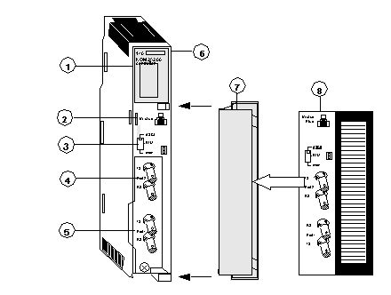
The following figure shows the parts of the Modbus Plus 140 NOM 252 00 module.
1 
LED Area
2 
Modbus Connector
3 
Comm Parameter Slide Switch
4 
Port 2 TX and RX Connectors
5 
Port 1 TX and RX Connectors
6 
Model Number, Module Description, Color Code
7 
Removable door
8 
Customer Identification Label, (Fold label and place it inside door)
Front Panel Switch
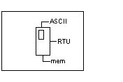
A three-position slide switch is located on the front of the unit. This switch is used to select the comm parameter settings for the Modbus (RS-232) port. Three options are available, as shown below.
The following figure shows the front panel switch.
Setting the slide switch to the top position assigns ASCII functionality to the port; the following comm parameters are set and cannot be changed.
ASCII Comm Port Parameters
The following table shows the fixed setting of the ASCII comm port parameters.
Baud
2,400
Parity
Even
Data Bits
7
Stop Bits
1
Device Address
Rear panel rotary switch setting
Setting the slide switch to the middle position assigns remote terminal unit (RTU) functionality to the port; the following comm parameters are set and cannot be changed:
RTU Comm Port Parameters
The following table shows the RTU comm port parameters.
Baud
9,600
Parity
Even
Data Bits
8
Stop Bits
1
Device Address
Rear panel rotary switch setting
Setting the slide switch to the bottom position gives you the ability to assign comm parameters to the port in software; the following parameters are valid.
Valid Comm Port Parameters
The following table shows the valid comm port parameters.
Baud
19,200
1,200
9,600
600
7,200
300
4,800
150
3,600
134.5
2,400
110
2,000
75
1,800
50
Data Bits
7 / 8
Stop Bits
1 / 2
Parity
Enable/Disable Odd/Even
Device Address
Rear panel rotary switch setting
Rear Panel Switches
Two rotary switches are located on the rear panel of the modules. They are used together to set the Modbus Plus node and Modbus port address for the unit.
NOTE: The highest address that may be set with these switches is 64.
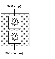
Rotary SW1 (top switch) sets the upper digit (tens), and rotary SW2 (bottom switch) sets the lower digit (ones) of the Modbus Plus node address. The illustration below shows the setting for an example address of 11.
SW1 and SW2 Switches Figure
The following figure shows the SW1 (top) and SW2 (bottom) switches.
SW1 and SW2 Address Settings
The following figure shows the node address settings for the SW1 and SW2 switches.
Node Address
SW1
SW2
1 ... 9
0
1 ... 9
10 ... 19
1
0 ... 9
20 ... 29
2
0 ... 9
30 ... 39
3
0 ... 9
40 ... 49
4
0 ... 9
50 ... 59
5
0 ... 9
60 ... 64
6
1 ... 4
NOTE: If "0" or an address greater than 64 is selected, the Modbus + LED will be "on" steady, to indicate the selection of an invalid address.
Modbus Connector
The NOM 252 00 module is equipped with an RS-232 port (see below) located on the front of the module. This port uses an eight-position RJ45 (phone jack-type) connector.
Modbus pin 1 Figure
The following figure shows the NOM 252 00 Pin 1 connector.
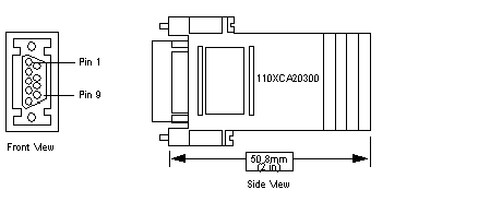
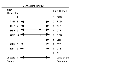
NOTE: A D-shell adapter is available from Modicon for NOM 252 00-to-computer connections: a (110 XCA 20 300) 9-pin adapter for PC-AT type computers (see the illustration pinout table below).
Pinouts Figures
The following figures show the 9-pin adapter front view (left) and side view (right).
Connector Pinouts Figure
The following figure shows the 9-pin RJ45 connector schematic.
BJ45 Cable Types
This following shows an example of the 110 XCA 282 0X cable. A table is also provided which includes part numbers and cable lengths.
RJ45 Connector Figure
The following figure shows the RJ45 connector (Modicon Part # 110 XCA 282 OX).
BJ45 Cable Part Numbers Table
Cable Part Numbers
Cable Lengths
110 XCA 282 01
3 ft. (0.91 m)
110 XCA 282 02
10 ft. (3 m)
110 XCA 282 03
20 ft. (6 m)