|
Presentation
|
|
|
Original instructions
|
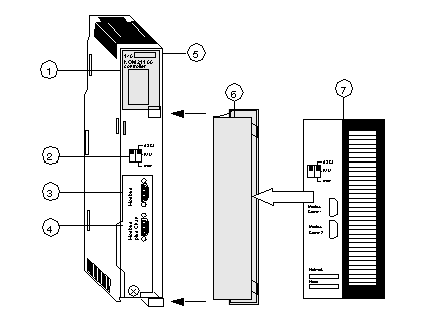
1LED Area
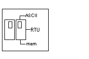
2Comm Parameter Slide Switch
3Modbus Connector
4Modbus Plus Connector
5Model Number, Module Description, Color Code
6Removable door
7Customer Identification Label, (Fold label and place it inside door)
|
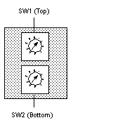
Node Address
|
SW1
|
SW2
|
|---|---|---|
|
1 ... 9
|
0
|
1 ... 9
|
|
10 ... 19
|
1
|
0 ... 9
|
|
20 ... 29
|
2
|
0 ... 9
|
|
30 ... 39
|
3
|
0 ... 9
|
|
40 ... 49
|
4
|
0 ... 9
|
|
50 ... 59
|
5
|
0 ... 9
|
|
60 ... 64
|
6
|
1 ... 4
|
|
Baud
|
2,400
|
|
Parity
|
Even
|
|
Data Bits
|
7
|
|
Stop Bits
|
1
|
|
Device Address
|
Rear panel rotary switch setting
|
|
Baud
|
9,600
|
|
Parity
|
Even
|
|
Data Bits
|
8
|
|
Stop Bits
|
1
|
|
Device Address
|
Rear panel rotary switch setting
|
|
Baud
|
19,200
|
1,200
|
|
|
9,600
|
600
|
|
|
7,200
|
300
|
|
|
4,800
|
150
|
|
|
3,600
|
134.5
|
|
|
2,400
|
110
|
|
|
2,000
|
75
|
|
|
1,800
|
50
|
|
Data Bits
|
7 / 8
|
|
|
Stop Bits
|
1 / 2
|
|
|
Parity
|
Enable/Disable Odd/Even
|
|
|
Device Address
|
Rear panel rotary switch setting
|
|
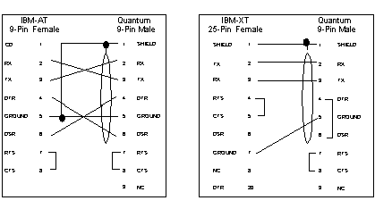
|
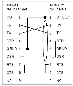
TX: Transmitted Data
|
DTR: Data Terminal Ready
|
|
RX: Received Data
|
CTS: Clear to Send
|
|
RTS: Request to Send
|
N/C: No Connection
|
|
DSR: Data Set Ready
|
CD: Carrier Detect
|
