Inputs for PTO
Original instructions
Overview
There are 4 auxiliary inputs for every PTO channel:
DANGER
HAZARD OF ELECTRIC SHOCK
  • disconnect voltage supplying sensors and pre-actuators before plugging / unplugging the terminal block on the module.
  • remove the terminal block before plugging / unplugging the module on the rack.
Failure to follow these instructions will result in death or serious injury.
Diagram
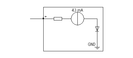
Drive_Ready&Emergency inputs or Counter_in_Position (SINK/SOURCE input type):
Origin or Proximity&LimitSwitch inputs (SINK input type):
Wiring the inputs
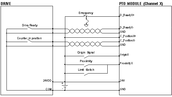
If the Drive_Ready&Emergency and Counter_in_Position outputs from the drive are of SINK type:
A twisted pair cable is necessary to connect the module to the drive.
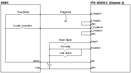
If the Drive_Ready&Emergency and Counter_in_Position outputs from the drive are of SOURCE type:
NOTE: In order to stop the PTO module when the PLC is set to STOP, connect the D_ReadyX+ input to the PTO module via a BMX DRA (0805 or 1605). This will make all outputs stop when the D_Ready&Emergency input is set to 0.
CAUTION
INSIGNIFICANT INPUT, SHORT-CIRCUIT OR OVERLOAD
Respect mounting and installation procedure and use the given wiring cable diagrams when using the PTO module.
Failure to follow these instructions can result in injury or equipment damage.