|
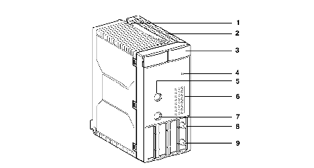
Physical presentation of the modules
|
|
|
(Original Document)
|

|
Number
|
Elements
|
Functions
|
|---|---|---|
|
1
|
Screw
|
Attaches the module to the TSX RKY •• rack
|
|
2
|
Module casing
|
Does the following:
• Supports and protects the electronic boards,
• Locks the module into its slot.
|
|
3
|
Display block comprising 6 LEDs:
• green RUN LED
• red ERR LED
• red I/O LED
• yellow SER LED
• yellow COM LED
• yellow INI LED
|
These enable the user to visualize the status and errors of the module.
Indicates the operating mode of the module.
Indicates an internal module error.
Indicates an external module error or an application error.
Indicates that traffic on the SERCOS® network is flowing correctly.
Not significant
Indicates that the module is in re-initialization phase.
|
|
4
|
Recessed button
|
Used to initialize the module.
|
|
5
|
COM2 8-pin Mini DIN connector
|
Reserved.
|
|
6
|
24 LED indicators
|
Used to visualize and diagnose the module channels.
|
|
7
|
COM1 8-pin Mini DIN connector
|
Reserved.
|
|
8
|
TX send SMA connector
|
Used to connect the send fiber optic cable of the SERCOS® ring network.
|
|
9
|
RX receive SMA connector.
|
Used to connect the receive fiber optic cable of the SERCOS® ring network.
|