|
Description of the example
|
|
|
(Original Document)
|

|
I/O
|
Description
|
|---|---|
|
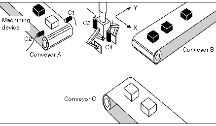
C1
|
Machined part detection cell
|
|
C2
|
Sensor to identify the part type.
|
|
C3
|
Grab open / grab closed detection sensor.
|
|
C4
|
Part edge detection cell (located in the grab), connected to the module’s event input.
|
|
ENC0
|
Incremental encoder in the X axis position.
|
|
ENC1
|
Incremental encoder in the Y axis position.
|
|
O/C grab
|
Open / close claw command.
|


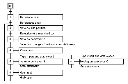
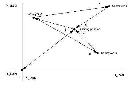
1Reference point at speed Vp0,
2Movement at speed Vret to the stand-by position (Xatt, Yatt) with stop,
3Movement towards belt A (XA, YA) at speed VA, as far as detection of the machined part,
4Movement towards conveyor B (XB, YB) at speed VB, with stop,
6Movement towards conveyor C (XC, YC) at speed VC, with stop,
5, 7Movement to waiting position (Xatt, Yatt) at speed Vret, with stop.

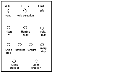
Auto/Man.Operating mode selection switch.
Starting cycleExecutes the automatic cycle.
Stop cycleStops the automatic cycle.
Select axis X / YSelects axis to be driven in manual mode.
Reference pointManual reference point on the selected axis.
Forward / BackControl for manual movement of the selected axis in a positive or negative direction.
FaultIndicator of all hardware faults and application errors.
Ack. FaultFault acknowledgement control.
Emergency stopImmediate stop of the moving part whatever the selected mode.
Open grabControl for opening grab.
Close grabControl for closing grab.