|
Encoder Type
|
|


|
(Original Document)
|
|
Encoder Type
|
|
|
(Original Document)
|
|
Parameter
|
Description
|
|---|---|
|
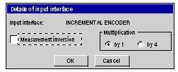
Measurement inversion
|
If you check this box, the direction in which the measurement changes will be reversed.
|
|
Multiplication by 1 or multiplication by 4
|
Multiplying by 4 increases the precision of the encoder:
The following diagram illustrates multiplication by 4
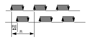 RE, corresponding to the resolution obtained by multiplication by 4, is also called equivalent resolution.
|
|
Parameter
|
Description
|
|---|---|
|
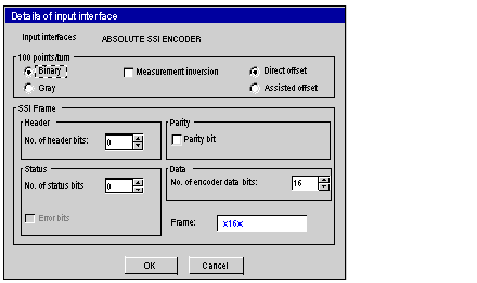
Direct offset or assisted offset
|
With a direct offset, you must specify the offset value in encoder points. With assisted offset, the offset is calculated by the module, using a position value supplied by the user. By default, direct offset is selected.
|
|
Binary or Gray
|
These selection buttons are used to define the code used by the encoder: binary code or Gray code (binary code by default).
|
|
Measurement inversion
|
This parameter defines the measurement inversion; in other words it defines direction in which the measurement changes for a given encoder rotation direction. This parameter is inaccessible from an infinite machine.
|
|
Parameter
|
Description
|
|---|---|
|
No. of header bits
|
Number of frame header bits (not significant): 0 to 4 (0 by default).
|
|
No. of encoder data bits
|
Number of frame data bits for the modules:
TSX CAY 21/41:16 to 25 (16 by default),
TSX CAY •2/33:12 to 25 (12 by default).
|
|
No. of status bits
|
Number of frame status bits: 0 to 3 (0 by default). If you choose a number of bits other than 0 it will give access to the error bit and its position (Position 1 to 3) in the status bits zone.
|
|
Presence of parity bit
|
Presence or absence of parity bit (absence by default). If this box is checked, you can define the type of parity: even or odd.
If you select odd parity, the module will no longer perform the parity check and the parity bit will be managed as a status bit.
|
|
Frame
|
Redisplays the characteristics defined for the SSI frame.
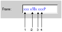 Addresses:
1 : number of header bits
2 : number of data bits
3 : number of status bits
4 : presence of parity bit P: parity, I: Odd
|
