Description of Speed Delta Parameters
These 3 parameters (one parameter for each interpolated axis) are used to set:
|
Adjustment
|
Meaning
|
|
Speed Delta X
Speed Delta Y
Speed Delta Z
|
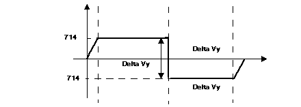
Variation of speed allowed on crossing points for each axis. The speed adjustment for the moving part at the crossing point allows the moving part to pass closer to the target point when the defined value is low.
These parameters are expressed as a thousandth of VMAX.
Limits: 0 to 500
|
Processing Crossing Points
In a linear interpolation, when a succession of non-stop G01 type movements are performed, the concept of crossing points becomes clear.
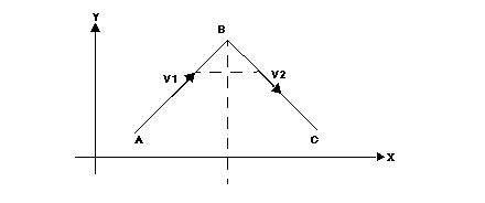
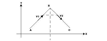
For example, let us assume that an ABC trajectory is required.
A specified speed maintained up to B on the AB segment causes an overshoot (figure 1). If the speed is reduced before arriving at B, then the real trajectory remains inside the ABC angle (figure 2).
How to Avoid Overshooting:
-
The natural delay (following deviation) of each axis is used. To do this, it is advised to moderate the feed forward gain adjustment KV during interpolated movements.
-
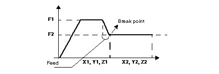
In a sequence (G01, X1, Y1, Z1, F1) followed by another sequence (G01, X2, Y2, Z2, F2), if F2 is smaller than F1, the speed trajectory is modified so that the desired speed is equal to F2 at the break point.
The following figure illustrates the modification of the speed trajectory so F2 speed is reached on the break point:
-
Role of the parameter: DELTASPEEDPATH
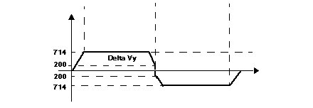
The module introduces a mechanism, which can reduce the speed at the point of crossing, according to the requested "Delta speed" (axial Delta speed X, Y or Z). The function is implemented from the point at which the VMAX can be adjusted.
The function is active when:

V
(of an axe) > VMAX * DELTASPEEDPATH/1000
NOTE: The smaller the DELTASPEEDPATH parameter, the closer the point.
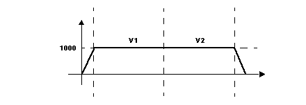
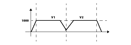
V1 = V2 = 1000
VMAXX = VMAXY = 4000
Axial speed X
(VX 2 + VY 2)1/2
Axial speed Y

V
Y < VMAX * DELTASPEEDPATH/1000
DELTASPEEDPATH = 500

V
Y = 1428 < 1/2 * VMAX
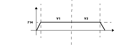
V1 = V2 = 1000
VMAXX = VMAXY = 4000
Axial speed X
(VX 2 + VY 2)1/2
Axial speed Y
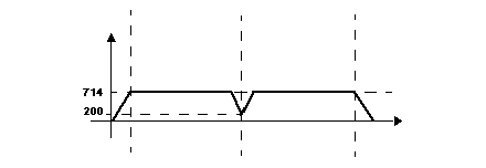
DELTASPEEDPATH = 100

V
Y = 1428 > 1/10 * VMAX
In this case a = 1/10 VMAX = 400

 V(of an axe) > VMAX * DELTASPEEDPATH/1000
 VY < VMAX * DELTASPEEDPATH/1000
  VY = 1428 < 1/2 * VMAX
 VY = 1428 > 1/10 * VMAX