|
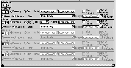
Configuration of a Slave Axis Group (Channels 21 to 24)
|
|
|
(Original Document)
|

|
Parameter
|
Description
|
|---|---|
|
Slave 1 (to 6)
|
Used to set the number of the slave axis (axes 1 to 12).
|
|
Measurement
|
When this button is checked, the slave axis follows the measured position of the master axis. This button operates alternately with the Setpoint button.
|
|
Setpoint
|
When this button is checked, the slave axis follows the position of the master axis setpoint. This button operates alternately with the Measurement button.
|
|
Gearing
|
When the button is checked, the slave axis follows the master axis in Ratio mode; that is to say following a ratio determined by the Ratio field. This button operates alternately with the Cam button.
|
|
Cam
|
When this button is checked, the slave axis follows the master axis in Cam mode; that is to say following the cam profile whose number is selected in the No. field. This button operates alternately with the Gearing button.
|
|
Ratio
|
In Ratio mode, these 2 fields are used to input the numerator and the denominator, which define the ratio between the master axis and the slave. These values are entered as floating points.
|
|
Start
|
Used to select the start condition:
|
|
No.
|
In Cam mode, this field is used to select the cam profile number (between 25 and 31).
|
|
Offset
|
In Cam mode, this field is used to input an offset value, which will be added to the master position, in order to define the position of the slave.
The resulting position of the slave will be given by the index in the cam profile master table. This index is equal to the current position of the master + offset (for example, a cam profile defined from 0 to 1000 for the master coordinates). To start following a master position equal to 100000, the offset value should be equal to -100000.0.
This offset is used, for example, to define a sine and cosine function from the same cam profile. This value is entered as a floating point.
|
|
Bias remains (residual)
|
When this box is checked:
|
|
Trigger
|
When the start condition is dependent on the position of the master axis in relation to a threshold, this field is used to input the threshold value. This value is entered as a floating point.
Activation will take place when the current position of the master + offset > (or <, >, <) the value of the threshold (Trigger).
|
|
Stop on follow-on
|
When this box is checked, confirming the link between the master and the slave will stop any possible additional movement of the slave axis, following a deceleration profile determined automatically.
|
|
Stop master/flt
|
When this box is checked, the master stops when there is a contour discrepancy (fault) between the master and the slave.
|