Configuring an Individual Axis (Channels 1 to 12)
(Original Document)
Introduction
Use Control Expert software to configure the TSX CSY 85 module.
An individual axis can be either a real axis (channels 1 to 8) or an imaginary axis (channels 9 to 12). The configuration of a real axis enables control of a physical axis (which uses a servodrive). In this case, a certain consistency must be ensured between the parameters entered in the TSX CSY 85 module configuration screen and those defined during servodrive configuration.
First configure the individual axes, two or three real axes and one axis that will then be used as the master of the real axes to be configured subsequently as slave axes.
In order to be able to use the new interpolation functions described in the rest of this documentation, you must observe the following rules:
Configuration Screen
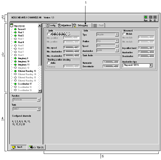
The Configuration screen for an individual axis appears below. There are 5 parameter entry zones: Limits, Enabling position checking, Units, Scale factor, and Movement.
The table below presents the different elements of the Configuration screen.
Address
Element
Function
1
Tabs
The tab in the foreground indicates the current mode (Debug in this example). Each mode can be selected using the corresponding tab. Available modes are:
  • Debug, accessible only in online mode,
  • Diagnostic (Default), accessible only in online mode,
  • Adjustment,
  • Configuration.
2
Module zone
Displays the short title of the module.
In the same zone there are 3 lamps showing the status of the module in online mode:
  • RUN shows the operating mode of the module.
  • ERR indicates an internal module error.
  • I/O indicates a fault outside the module or an application fault.
3
Channel zone
Allows you to:
  • display the tabs, by clicking on the device reference:
    • Description: provides the device characteristics.
    • I/O objects: provides a preview symbol of the input/output objects.
    • Default: gives access to the device defaults (in online mode).
  • choose the channel,
  • displays the Symbol, channel name defined by the user (via the variables editor).
4
General parameters zone
Used to unforce bits and view the counting function:
  • Unforce: button used to unforce forced bits.
  • Function: recalls the configured counting function. This information cannot be modified.
  • Task: displays the MAST or FAST task configured. This information cannot be modified.
5
Current parameters zone
This zone displays the I/O status and the different parameters for the count in progress. If the contents of the counting register cannot be used following an error on the inputs, the message or lamp Invalid measurement appears in red.
The remainder of this chapter describes the parameters of the current parameters zone
Limits Zone Parameters
Description
Parameters
Description
Position checking
For a limited machine, this checkbox can be used to enable the position limit check. The axis position is compared with the position limits defined during configuration. When the axis reaches one of its limits, its movement is stopped and an error is generated.
For an infinite axis, this box should not be checked.
Max. position
Maximum position limit. This value is entered as a floating point.
Min. position
Minimum position limit. This value is entered as a floating point.
Max. speed
Maximum permissible speed. This value is independent of the value defined in the servodrive (real axis). This value is entered as a floating point. Setting the maximum speed to 0 disables speed monitoring.
Max. acceleration
Maximum permissible acceleration. This value is independent of the value defined in the servodrive (real axis). This value is entered as a floating point.
Max. deceleration
Maximum permissible deceleration. This value is independent of the value defined in the servodrive (real axis). This value is entered as a floating point.
Enabling Position Checking Zone Parameters
Description
Parameters
Description
Active
This checkbox can be used to enable position checking.
When the axis is disabled:
  • If its movement is less than the tolerance, the axis returns to its last position when it is reactivated.
  • If its movement is greater than the tolerance, the axis remains in its new position when it is reactivated.
Tolerance
Value of the monitoring window. This value is entered as a floating point.
Units Zone Parameters
Description
Parameters
Description
Type
Type of physical units used to express the position, speed and acceleration readings: Angular, Linear, Linear English or Encoder points.
Position
Position unit
  • Angular: mrad, rad, deg, arcmin, revs
  • Linear: μm, mm, cm, m
  • Linear English: in, ft, yd, mile
  • Encoder points: points.
Speed
Speed unit.
  • Angular: mrad/s, rad/s, rad/min, deg/s, deg/min, arcmin/s, revs/s, revs/min
  • Linear: μm/s, mm/s, mm/min, cm/s, cm/min, m/s, m/min
  • Linear English: in/s, in/min, ft/s, ft/min, yd/min, mile/s
  • Encoder points: points/ms, points/s, points/min
Acceleration
Acceleration unit.
  • Angular: mrad/s2, rad/s2, deg/s2, arcmin/s2, revs/s2, revs/min/s
  • Linear: μm/s2, mm/s2, cm/s2, m/s2, m/min2, g’s
  • Linear English: in/s2, ft/s2, yd/min2, mil/s2
  • Encoder points: points/ms2, points/s2
Scale Factor Zone Parameters
Description
Parameter
Description
Numerator
Scale factor numerator. This value is entered as a floating point.
Denominator
Scale factor denominator. This value is entered as a floating point.
Movement Zone Parameters
Description
Parameter
Description
Modulo
For an infinite axis, this checkbox can be used to activate the modulo function.
Max. modulo
Upper modulo limit. This value is entered as a floating point.
Min. modulo
Lower modulo limit. This value is entered as a floating point.
In-position band
Value of the in-position band. This value is entered as a floating point.
Acceleration
Acceleration value defined for a movement. This value is entered as a floating point.
Deceleration
Deceleration value defined for a movement. This value is entered as a floating point.
Acceleration type
Acceleration type: Rectangle 100%, Trapezoid 125%, Trapezoid 150%, Trapezoid 175% or Triangle 200%.
Rescaling
For a servodrive whose position is defined in angular units (degrees) the module performs a rescaling operation according to its reference, which is measured in revolutions, and its speed, which is measured in revolutions/second.
For example, if the axis is configured as angular axis with a scale factor of 1/1:
Changing the Unit Type
When the type of unit is changed in relation to the servodrive, which remains in revolutions, the reference unit of the module is mm (linear type) and inches (linear English type). The transformation achieved by the module is equal to:
For example, if the axis is configured as linear with a scale factor of 1/1:
Using the Scale Factor
Consider an application where the axis moves a belt: for instance, 1 axis revolution moves the belt 100 mm. If you wish to express the position in mm: